
Implementation method for reducing beam width of heading beacon array antenna

A beamwidth and navigation beacon technology, applied in the field of navigation beacons, can solve the problems of single means, high cost, and long procurement time period.

Pending Publication Date: 2021-04-09
THE SECOND RES INST OF CIVIL AVIATION ADMINISTRATION OF CHINA
View PDF5 Cites 2 Cited by
  • Summary
  • Abstract
  • Description
  • Claims
  • Application Information

AI Technical Summary

Problems solved by technology

Moreover, the common method used by equipment operation units to reduce the channel CSB beamwidth at this stage is to select multi-element wide-aperture narrow-beam heading antennas, and the method is very simple.
In addition, for airports where large obstacles enter the CSB beam width of the localizer channel and have caused unacceptable impact on the channel structure, the equipment operating unit can only deal with the affected obstacle (remove the obstacle or cover the surface of the object with other materials to change its reflection characteristics, which is expensive and difficult) or replace the large-aperture antenna as a whole (the update equipment must reach a certain number of years, and it is imported equipment, and the procurement period is long), but this is often difficult. realized

Method used


Image

  • Implementation method for reducing beam width of heading beacon array antenna
  • Implementation method for reducing beam width of heading beacon array antenna
  • Implementation method for reducing beam width of heading beacon array antenna

Examples


Embodiment Construction

[0032] In order to make the object, technical solution and advantages of the present invention clearer, the present invention will be further described in detail below in conjunction with the accompanying drawings. Apparently, the described embodiments are only some of the embodiments of the present invention, but not all of them. Based on the embodiments of the present invention, all other embodiments obtained by persons of ordinary skill in the art without making creative efforts belong to the protection scope of the present invention.

[0033] In the description of the present invention, it should be noted that the terms "center", "upper", "lower", "left", "right", "vertical", "horizontal", "inner", "outer" etc. The indicated orientation or positional relationship is based on the orientation or positional relationship shown in the drawings, and is only for the convenience of describing the present invention and simplifying the description, rather than indicating or implying...


PUM


Abstract

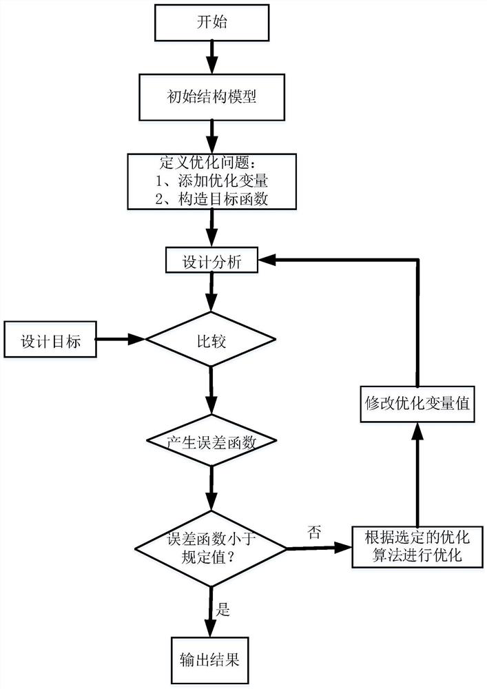
The invention discloses an implementation method for reducing the beam width of a heading beacon array antenna, and belongs to the technical field of heading beacons. The implementation method comprises the following steps: selecting a course beacon antenna array needing to be optimized, constructing an initial structure model, and generating a navigation channel CSB directional diagram; calculating the beam width according to the channel CSB directional diagram, and taking the fact that the beam width reaches or is smaller than a certain determined value as a target function; defining the interval between the arrays and the feed level amplitude of the arrays as optimization variables, changing the interval between the arrays or the feed level of the arrays, observing the change trend of a channel CSB directional diagram, and defining an initial value, a minimum value and a maximum value for the optimization variables in combination with a target function; submitting design analysis; comparing with a design target to generate an error function; and outputting a result if the error function is smaller than a specified value. By adopting the method provided by the invention, the CSB signal beam width of the heading beacon can be reduced under the condition of not increasing the number of antenna arrays.

Description

technical field [0001] The invention belongs to the technical field of course beacons, and in particular relates to a realization method for reducing the beam width of a course beacon array antenna. Background technique [0002] The Instrument Landing System (ILS) is a widely used precision approach and landing guidance system. In the late 1940s, the International Civil Aviation Organization (ICAO) adopted ILS as the standard approach and landing guidance system. ILS usually includes: Localizer (Frequency Band: 108-112MHz), Glide Path (Frequency Band: 328-334MHz) and Distance Measuring Equipment (Frequency Band: 960-1215MHz). Among them, the localizer provides the horizontal guidance signal during the aircraft's precise approach, the glide beacon provides the vertical guidance signal, and the range finder provides the distance information. [0003] The localizer antenna is generally set on the extension line of the runway centerline, 180-600m away from the end of the runwa...

Claims


Application Information

Patent Timeline
IPC IPC(8): G06F30/20
CPCG06F30/20
Inventor 叶家全袁斌梁飞李沅锴杨萍李清栋林欢许健孙彦龙李润文施瑞
Owner THE SECOND RES INST OF CIVIL AVIATION ADMINISTRATION OF CHINA
Learn More