
Battery pole piece laminating equipment and battery cell laminating method

A battery pole piece and lamination technology, which is applied in battery assembly, secondary battery manufacturing, climate sustainability, etc., can solve the problems of reducing the qualified rate of battery products and the inability of pole piece insulation to be guaranteed, and avoid the The effect of pulling, increasing the amount of cache, and avoiding accumulation

Active Publication Date: 2021-04-09
SVOLT ENERGY TECHNOLOGY CO LTD
View PDF7 Cites 3 Cited by
  • Summary
  • Abstract
  • Description
  • Claims
  • Application Information

AI Technical Summary

Problems solved by technology

However, the battery pole piece enters the heat-sealing mechanism to form an integrated battery pole piece after passing through the feeding unit. The movement speed at the heat-sealing mechanism is uniform, while the lamination speed of the lamination unit downstream of the heat-sealing mechanism is variable. The different speeds cause the lamination unit The claws are easy to pull the separator tape of the battery pole piece, so that the insulation between the pole pieces cannot be guaranteed, and the qualified rate of the battery product is reduced.

Method used


Image

  • Battery pole piece laminating equipment and battery cell laminating method
  • Battery pole piece laminating equipment and battery cell laminating method
  • Battery pole piece laminating equipment and battery cell laminating method

Examples


Embodiment Construction

[0045] In order to make the technical problems solved by the present invention, the technical solutions adopted and the technical effects achieved clearer, the technical solutions of the embodiments of the present invention will be further described in detail below in conjunction with the accompanying drawings. Obviously, the described embodiments are only the technical solutions of the present invention. Some, but not all, embodiments. Based on the embodiments of the present invention, all other embodiments obtained by those skilled in the art without making creative efforts belong to the protection scope of the present invention.

[0046] In the description of the present invention, unless otherwise clearly specified and limited, the terms "connected", "connected" and "fixed" should be understood in a broad sense, for example, it can be a fixed connection, a detachable connection, or an integrated ; It can be a mechanical connection or an electrical connection; it can be a d...


PUM


Abstract

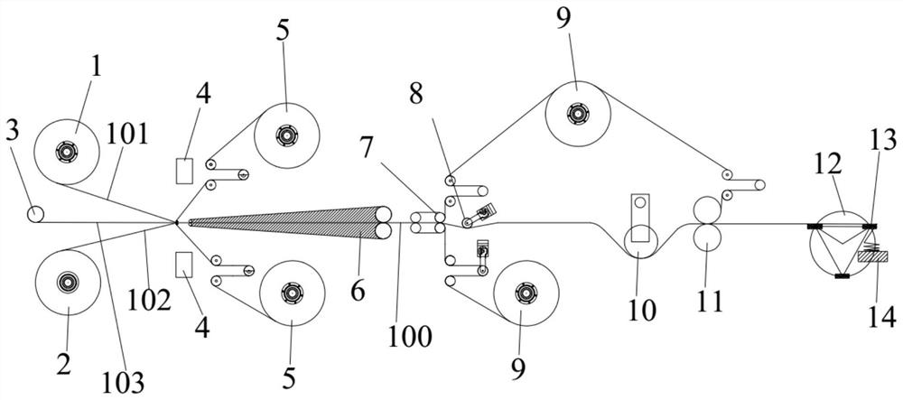
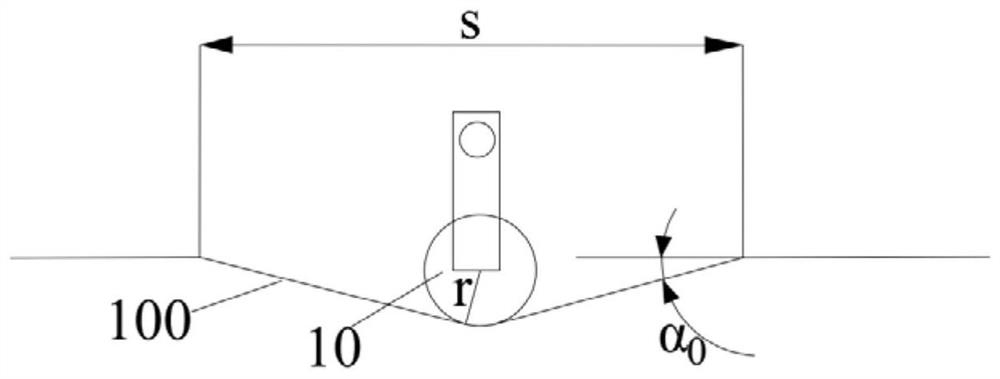
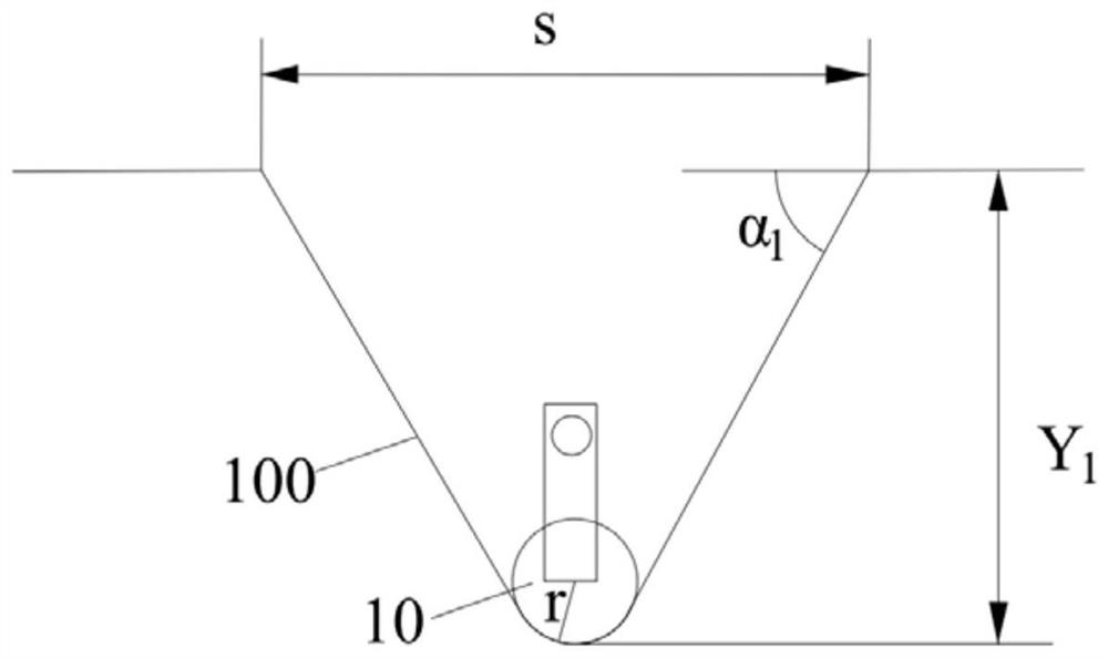
The invention relates to the technical field of power battery manufacturing, and discloses battery pole piece laminating equipment and a battery cell laminating method, a battery pole piece comprises a positive pole piece, a negative pole piece and a diaphragm strip material, and the positive pole piece and the negative pole piece are correspondingly arranged on two sides of the diaphragm strip material. The battery pole piece laminating equipment comprises a heat sealing unit, a buffering unit, a laminating unit and a driving unit. And the heat sealing unit is arranged at the downstream of the feeding unit and is used for heating and pressing the battery pole piece. The buffering unit is arranged at the downstream of the heat sealing unit and comprises a buffering roller and a lifting driving piece, and the lifting driving piece can drive the buffering roller to ascend or descend so as to reduce or increase the buffer length of the battery pole piece. The lamination unit is arranged at the downstream of the buffering unit and is used for folding the battery pole piece, the lamination unit comprises a turret mechanism and a lamination platform, the turret mechanism comprises a turntable and a clamping jaw, the clamping jaw can clamp the battery pole piece, and the turntable can drive the clamping jaw to rotate to the lamination platform. The battery pole piece laminating equipment can adapt to the changed lamination speed, and the quality and the qualification rate of battery cell products are improved.

Description

technical field [0001] The invention relates to the technical field of power battery manufacturing, in particular to a battery pole sheet stacking device and a cell stacking method. Background technique [0002] In the environment of the automobile industry that uses traditional energy as power supply, the problem of environmental pollution is becoming more and more serious. Actively developing new energy vehicles can reduce the harm to the environment. Lithium-ion device technology is a key technology for the development of electric vehicles. Batteries with square laminates are widely used, and the speed of lamination directly determines the production capacity of the whole line and the manufacturing cost of batteries. At present, most of them use z-type lamination technology. The world’s fastest lamination speed that has been mass-produced is 0.6s / piece. Using this lamination method is relatively slow, resulting in a large demand for equipment, a large footprint, and a hi...

Claims


Application Information

Patent Timeline
IPC IPC(8): H01M10/04
CPCH01M10/0404Y02P70/50
Inventor 赵凯李昆芃汪常江新海
Owner SVOLT ENERGY TECHNOLOGY CO LTD
Learn More