
Brake control device, brake control system, and control method

A technology of brake control and control method, which is applied in the direction of brake transmission device, brake action activation device, foot activation device, etc., which can solve the problems of inability to boost pressure, deterioration of braking effect, and drop, and achieve guaranteed Safety requirements, meeting braking requirements, and improving safety effects

Pending Publication Date: 2021-04-09
HUAWEI TECH CO LTD
View PDF10 Cites 1 Cited by
  • Summary
  • Abstract
  • Description
  • Claims
  • Application Information

AI Technical Summary

Problems solved by technology

However, in the existing two-way pressure building scheme, when switching from forward pressure building to reverse pressure building, there will be a situation where the pressure cannot be increased for a period of time or even the pressure will drop temporarily, resulting in the inability to continuously provide braking force and affecting the braking effect.
In short, there are defects in the pressure building process of the existing two-way pressure building scheme, resulting in poor braking effect

Method used


Image

  • Brake control device, brake control system, and control method
  • Brake control device, brake control system, and control method
  • Brake control device, brake control system, and control method

Examples


Embodiment Construction

[0072] The technical solution in this application will be described below with reference to the accompanying drawings.

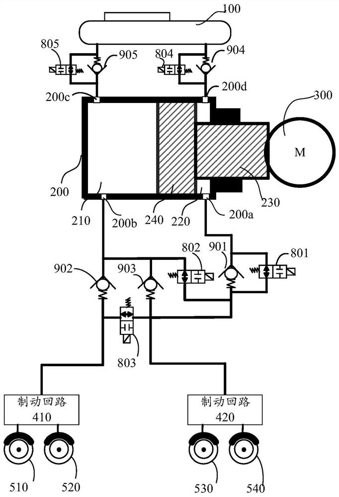
[0073] figure 1 It is a schematic structural diagram of a traditional brake control system with bidirectional supercharging function. figure 1 The brake control system shown includes a drive device 300, a brake circuit 410, a brake circuit 420, a fluid storage device 100, a hydraulic cylinder 200, a piston 240, a push rod 230, a second hydraulic chamber 220, a first hydraulic chamber 210, Ports 200a and 200d of the second hydraulic chamber 220, ports 200c and 200b of the first hydraulic chamber 210, and several control valves and check valves.

[0074] The brake circuit 410 is used to provide braking force to the wheels 510 and 520 , and the brake circuit 420 is used to provide braking force to the wheels 530 and 540 .

[0075] like figure 1 As shown, the driving device 300 is used to drive the push rod 230 to push the piston 240 to move along the inner w...


PUM


Abstract

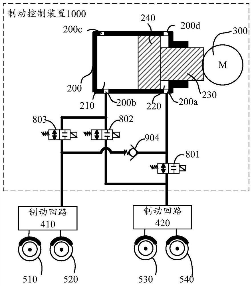
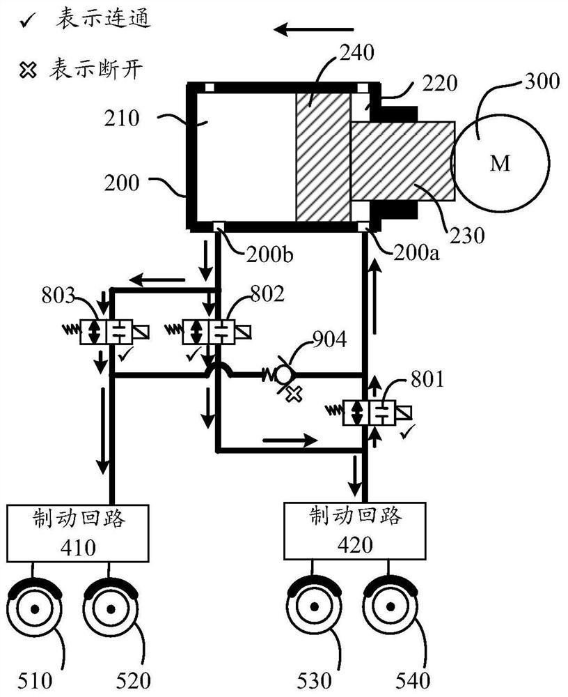
The invention provides a brake control device, a brake control system and a control method. The invention is suitable for intelligent automobiles, new energy automobiles or traditional automobiles and the like. The brake control device comprises a hydraulic cylinder, a push rod, a piston, a driving device, a first control valve, a second control valve, a third control valve and a fourth valve. A plurality of valves and a specific connecting mode are arranged, so that two hydraulic cavities communicate with each other during forward pressure buildup, and the two hydraulic cavities do not communicate with each other during backward pressure buildup; the hydraulic pressure in the two hydraulic cavities is kept equal or the pressure difference is very small, so that seamless switching between forward pressure buildup and backward pressure buildup can be achieved, and the braking requirement of a vehicle is better met; in addition, each braking loop can be independently controlled to be connected or disconnected, safety is improved, in other words, the safety is improved through the specific connecting mode, and the number of valves is reduced as much as possible.

Description

technical field [0001] The present application relates to the field of automobiles, and more specifically, to a brake control device, a brake control system and a control method in an automobile. Background technique [0002] The braking system of a car is a system that applies a certain braking force to the wheels of the car to perform a certain degree of mandatory braking. The function of the brake control system is to make the driving car decelerate or even stop forcibly according to the requirements of the driver or the controller, or to make the stopped car stably park under various road conditions (for example, on a slope), or Keep the speed of the car downhill steady. [0003] The braking system can increase or decrease the pressure of the brake fluid in the braking system based on the driving needs of the vehicle. For example, when the brake system works in the control-by-wire mode, when the driver depresses the brake pedal, the brake control device in the brake sy...

Claims


Application Information

Patent Timeline
Patent Type & Authority Applications(China)
IPC IPC(8): B60T8/40B60T13/14B60T7/04B60T7/06
CPCB60T8/409B60T8/40B60T13/14B60T7/042B60T7/06B60T13/745B60T13/686B60T13/66B60T13/662B60T13/68B60T15/028B60T15/043B60T15/045B60T15/36B60T7/12B60T17/221
Inventor 陈效华张永生刘亚林
Owner HUAWEI TECH CO LTD
Learn More