Electric branch binding machine

A branch binding machine and electric technology, applied in the application, cultivation, agriculture and other directions, can solve problems such as affecting normal use, affecting the effect of binding branches, easy to run wire, etc. Effect

Pending Publication Date: 2021-04-13
南通捷顺电动工具有限公司
View PDF7 Cites 0 Cited by
  • Summary
  • Abstract
  • Description
  • Claims
  • Application Information

AI Technical Summary

Problems solved by technology

[0003] Existing electric tying machines have the following defects: 1. The bracket body and the connector part of the driving structure of the wire feeding cutting bracket structure of the tying machine on the market are integrated structures, and then the cutting piece is installed on the bracket body. As well as the cover plate, although the one-piece structural design is convenient for casting and saves assembly time, once the iron wire is stuck in the wire feeding and cutting bracket structure, it cannot be disassembled to remove the stuck inside iron wire, which will affect the normal use in the later stage;
[0004] 2. The bracket body adopts a single-piece hook structure, and the iron wire forms an iron ring in the hook body, so as to realize the purpose of binding branches and vines. For example, the head cover structure in the patent No. 201821945426 forms a return-shaped track in the head cover structure. However, this structural design will have the defect of easy running wire, which will be off the runway and affect the binding effect; at present, the electric binding machine has a control circuit board to adjust the number of binding turns and the binding tightness of the binding machine, especially for binding The looser electric tying machine has more serious wire running phenomenon

Method used

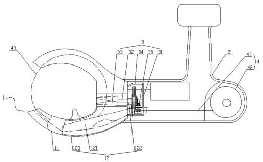
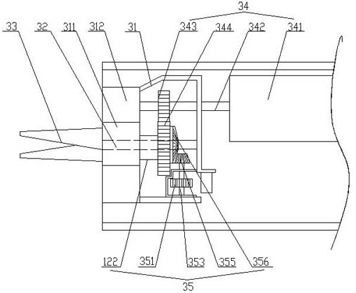
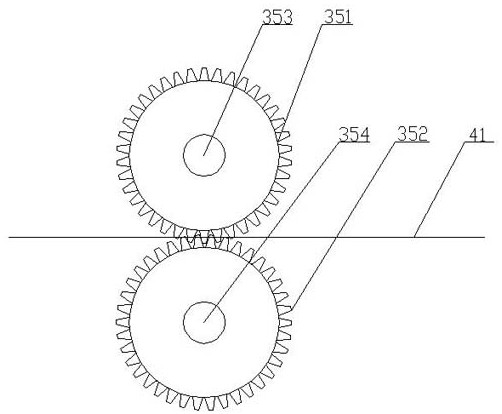

Image

  • Electric branch binding machine
  • Electric branch binding machine
  • Electric branch binding machine

Examples


Embodiment Construction

[0035] In order to deepen the understanding of the present invention, the present invention will be further described below in conjunction with the embodiments and accompanying drawings. The embodiments are only used to explain the present invention and do not constitute a limitation to the protection scope of the present invention.

[0036] In the description of the present invention, it should be understood that the terms indicating orientation or positional relationship, such as based on the orientation or positional relationship shown in the drawings, are only for the convenience of describing the present invention and simplifying the description, rather than indicating or implying the Structures or units must have a specific orientation and thus should not be construed as limiting the invention.

[0037] In the present invention, unless otherwise clearly specified and limited, terms such as "connected", "provided" and "had" should be understood in a broad sense, for exampl...


PUM


Abstract

The invention relates to an electric branch binding machine. The electric branch binding machine comprises a machine shell, a driving structure, a wire feeding structure and a wire feeding and cutting bracket structure, an iron wire on the wire feeding structure forms multiple circles of iron rings into the wire feeding and cutting bracket structure along with transmission of the driving structure, and the wire feeding and cutting bracket structure cuts off the multiple circles of iron rings; and one end of the driving structure is sleeved with a connecting piece, the connecting piece is detachably connected with the wire feeding and cutting bracket structure, a shift rail penetrates through the central direction of the connecting piece and is connected with the wire feeding cutting bracket structure, shifting forks are arranged at the two ends, close to the side end face of the wire feeding and cutting bracket structure, of the shift rail, when the shift rail rotates along with driving of a gear motor, a first bevel gear and a second bevel gear are driven to be in meshed transmission, and therefore an upper gear and a lower gear are meshed and drive the iron wire to be conveyed. The electric branch binding machine has the following advantages that the driving stability and synchronism are improved, the split bracket serves as a wire feeding rail, wire running is not likely to happen, and mounting, dismounting and later maintenance are convenient.

Description

Technical field: [0001] The invention belongs to the field of electric tools, and in particular relates to an electric branch binding machine. Background technique: [0002] The tying machine is a manual tool used to bind and fix the branches and vines of crops, fruit trees, flowers, etc. It is used to replace the traditional manual method of fixing them one by one with soft non-picking or straps, which is conducive to crop production to increase crop yield and Quality, while improving work efficiency, effectively saving labor costs. [0003] Existing electric tying machines have the following defects: 1. The bracket body and the connector part of the driving structure of the wire feeding cutting bracket structure of the tying machine on the market are integrated structures, and then the cutting piece is installed on the bracket body. As well as the cover plate, although the one-piece structural design is convenient for casting and saves assembly time, once the iron wire is...

Claims


Application Information

Patent Timeline
Patent Type & Authority Applications(China)
IPC IPC(8): A01G17/08A01G17/12
CPCA01G17/08A01G17/12
Inventor 陶成斌
Owner 南通捷顺电动工具有限公司
Why Eureka
Try Eureka