Micro-bubble generation device, and micro-bubble generation control method and device

A micro-bubble generation, gas-liquid technology, applied in the direction of mixing methods, chemical instruments and methods, transportation and packaging, etc., can solve the problems of fluid dissipation energy increase, micro-bubble size dispersion, micro-bubble coalescence, etc. Increase and decrease fluid energy dissipation and avoid coalescence effects

Pending Publication Date: 2021-04-13
CHINA PETROLEUM & CHEM CORP +1
View PDF7 Cites 5 Cited by
  • Summary
  • Abstract
  • Description
  • Claims
  • Application Information

AI Technical Summary

Problems solved by technology

[0003] The crushing of microbubbles in existing microbubble generators mostly uses internal components or swirl devices, which have the following problems: (1) the energy dissipation of the fluid is increased, and the internal components easily lead to the accumulation of microbubbles while crushing the bubbles; And; (2) The liquid flow cannot effectively shear and break the bubbles generated at the air inlet, and large bubbles are easy to form; (3) The size of the formed microbubbles is discrete, and the diameter of the bubbles is close to the millimeter level or contains a large number of microbubbles with a diameter of Millimeter-sized bubbles; difficult to control microbubble diameter and low gas fraction

Method used


Image

  • Micro-bubble generation device, and micro-bubble generation control method and device
  • Micro-bubble generation device, and micro-bubble generation control method and device
  • Micro-bubble generation device, and micro-bubble generation control method and device

Examples


Embodiment 1

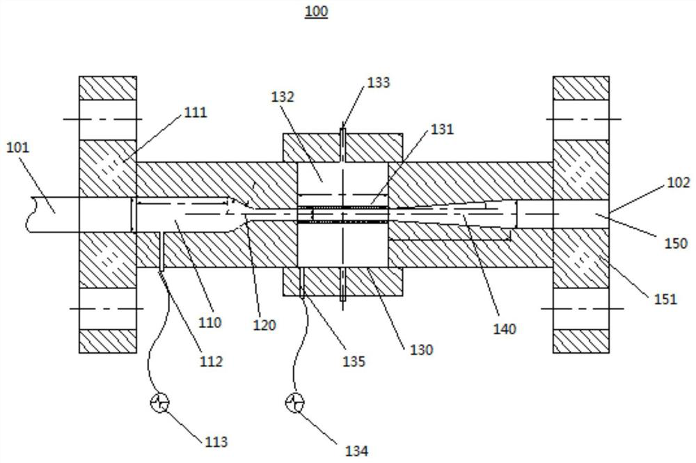
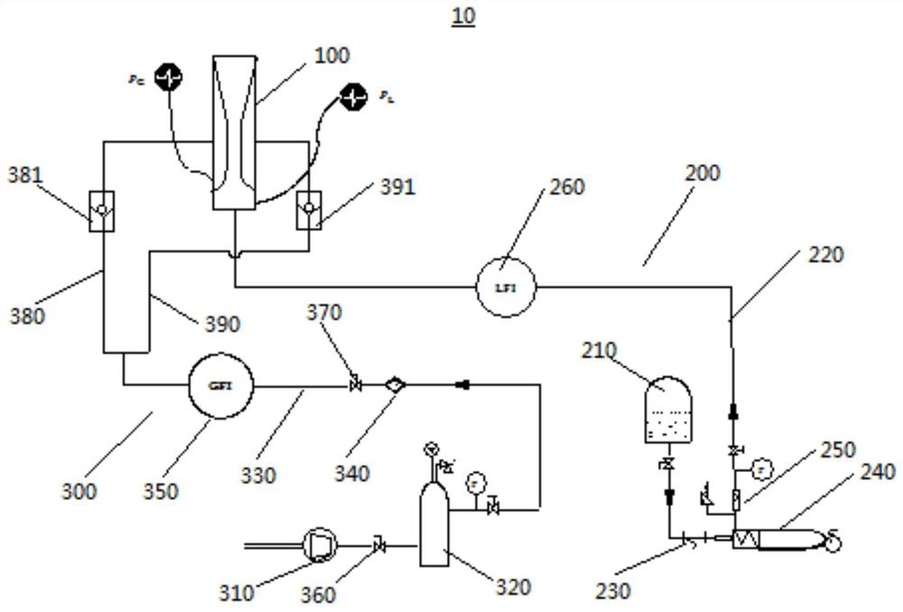
[0044] This embodiment provides a microbubble generation control device, the structure of which is shown in figure 1 , the specific parameters are as follows:

[0045] The liquid inlet section 110 has a diameter of 14 mm and a length of 60 mm. A liquid pressure measuring hole 112 with a diameter of 5 mm is installed in the middle of the liquid inlet section 110 near the liquid inlet 101 and is connected to a liquid pressure measuring sensor 113 .

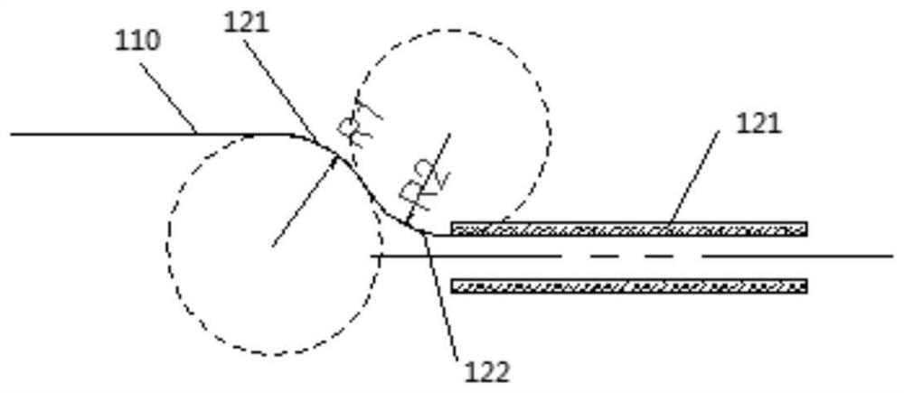
[0046] The arc radius R of the first arc 121 of the contraction section 120 1 is 7mm, the arc radius R of the second arc 122 2 is 10 mm, and the two arcs are tangent to the liquid inlet section 110 and the gas distribution porous pipe 131 respectively.

[0047] The upper and lower sides of the air intake section 130 are respectively equipped with an air intake hole 133 with a diameter of 4 mm, and the air intake section 130 close to the contraction section 120 is equipped with a gas pressure measuring hole 135 with a diameter of 3...

Embodiment 2

[0052] This embodiment provides a microbubble generation control device, which differs from Embodiment 1 only in that: the diameter of the liquid inlet section 110 is 30 mm, the length is 140 mm, the diameter of the liquid pressure measuring hole 112 is 8 mm; the first circle of the contraction section 120 Arc radius R of arc 121 1 is 15mm, the arc radius R of the second arc 122 2 21mm; the diameter of air inlet 133 on the upper and lower sides of air intake section 130 is 10mm, and the diameter of gas pressure measuring hole 135 is 8mm; the inner diameter of gas distribution porous pipe 131 is 20mm, the aspect ratio is 5, and the wall thickness is 8mm. The gas distribution porous tube 131 has a pore diameter of 300 μm; the angle between the contour line of the expansion section 140 and the axis is 5°, and the length of the expansion section 140 is 100 mm; the gas-liquid expansion section 150 has a diameter of 37.5 mm and a length of 100 mm; except for the gas distribution por...

Embodiment 3

[0055] This embodiment provides a microbubble generation control device, which differs from Embodiment 1 only in that: the diameter of the liquid inlet section 110 is 12 mm, the length of the liquid inlet section 110 is 80 mm, the diameter of the liquid pressure measuring hole 112 is 5 mm; the contraction section 120 The arc radius R of the first arc 121 1 is 6mm, the arc radius R of the second arc 122 2 The diameter of the air inlet 133 on both sides of the upper and lower sides of the air inlet section 130 is 4mm, and the diameter of the gas pressure measuring hole 135 is 2mm; the inner diameter of the gas distribution porous tube 131 is 4mm, the aspect ratio is 1, and the wall thickness is 2mm. The gas distribution porous tube 131 has a pore diameter of 3 μm; the angle between the outline of the expansion section 140 and the axis is 3°, and the length of the expansion section 140 is 40 mm; the gas-liquid expansion section 150 has a diameter of 8.2 mm and a length of 50 mm; ...


PUM

PropertyMeasurementUnit
diameteraaaaaaaaaa
thicknessaaaaaaaaaa
thicknessaaaaaaaaaa

Abstract

The invention discloses the technical field of petrochemical engineering, and relates to a micro-bubble generation device, and a micro-bubble generation control method and device. Liquid materials pass through a contraction section, then enter a gas distribution perforated pipe on an gas inlet section, gas and liquid are mixed in the gas distribution perforated pipe, and then a mixture enters an expansion section and a gas-liquid expansion section. According to the micro-bubble generating device, a Venturi tube and micropore distribution principle is utilized, micro-bubbles with high dispersion are formed, fluid effectively shears and crushes the bubbles, and large bubbles are crushed under the action of pressure recovery in the micro-bubble generating device to form the micro-bubbles; and an internal component or a rotational flow device is not adopted, fluid energy dissipation is effectively reduced, coalescence of tiny bubbles is also avoided, and the micro-bubble fraction is remarkably increased.

Description

technical field [0001] The invention relates to the technical field of petrochemical industry, and in particular to a microbubble generating device, a method and a device for controlling microbubble generation. Background technique [0002] In the chemical, biological and environmental fields, gas-liquid phase reactions exist widely, and mass transfer through bubble dispersion has been widely used. For gas-liquid reaction processes controlled by mass transfer rate such as hydrogenation and oxidation, the use of microbubbles to enhance mass transfer has important practical value. For the gas-liquid mass transfer process, microbubbles have a huge gas-liquid contact area per unit volume to enhance mass transfer, and microbubbles have a small volume, which makes them less lift. Therefore, microbubbles can improve the contact efficiency of gas-liquid devices, and can be applied in equipment such as bubble columns, reactors, gas absorption and fermentation tanks. The premise of ...

Claims


Application Information

Patent Timeline
Patent Type & Authority Applications(China)
IPC IPC(8): B01F3/04B01F5/04B01F15/00
CPCB01F23/235B01F23/232B01F23/291B01F25/3125B01F25/31242B01F35/2213
Inventor 陈强宋军超李立权刘金龙王龙延李治陈险峰李鹏程魏嘉
Owner CHINA PETROLEUM & CHEM CORP
Why Eureka
Try Eureka