Cyclone type micro-bubble generator and gas-liquid reactor

A technology of micro-bubble generator and gas-liquid reactor, which is applied in chemical methods, fluid mixers, chemical/physical/physical-chemical stationary reactors for reacting liquid and gas medium, etc., can solve the problem of bubble size dispersion. , difficult to manufacture, high energy consumption, to achieve the effect of reduced bubble size, simple structure and low energy consumption

Active Publication Date: 2019-04-02
ZHEJIANG UNIV
View PDF10 Cites 10 Cited by
  • Summary
  • Abstract
  • Description
  • Claims
  • Application Information

AI Technical Summary

Problems solved by technology

However, the smaller the particle size of the air bubbles, the smaller the pore size of the medium is required, and the requirements for the manufacturing and processing of the device are relatively high, and it is easy to cause blockage
[0006] To sum up, the existing micro-bubble generation devices have disadvantages such as difficult manufacturing, discrete bubble sizes, and high energy consumption.

Method used


Image

  • Cyclone type micro-bubble generator and gas-liquid reactor
  • Cyclone type micro-bubble generator and gas-liquid reactor
  • Cyclone type micro-bubble generator and gas-liquid reactor

Examples


Embodiment 1

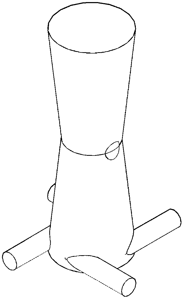
[0034] This embodiment adopts as figure 1 The microbubble generating device shown is used to prepare microbubbles. Among them, the number of liquid inlet pipes is 2, the diameter is 6mm, and the length is 30mm. Air is used as the gas experiment medium, and water is used as the liquid experiment medium. Air velocity at the air inlet u g =0.24m / s, the liquid velocity at the throat increased from 0.32m / s equivalent to 1.6m / s, and the bubbles generated by the microbubbles were photographed with a high-speed camera, and the statistically obtained microbubble fraction changes with the liquid velocity as follows: Figure 7 As shown, it can be seen from the figure that when the throat liquid velocity is greater, the microbubble fraction is higher, and when the throat liquid velocity u l =1.6m / s, microbubble fraction η=65%.

Embodiment 2

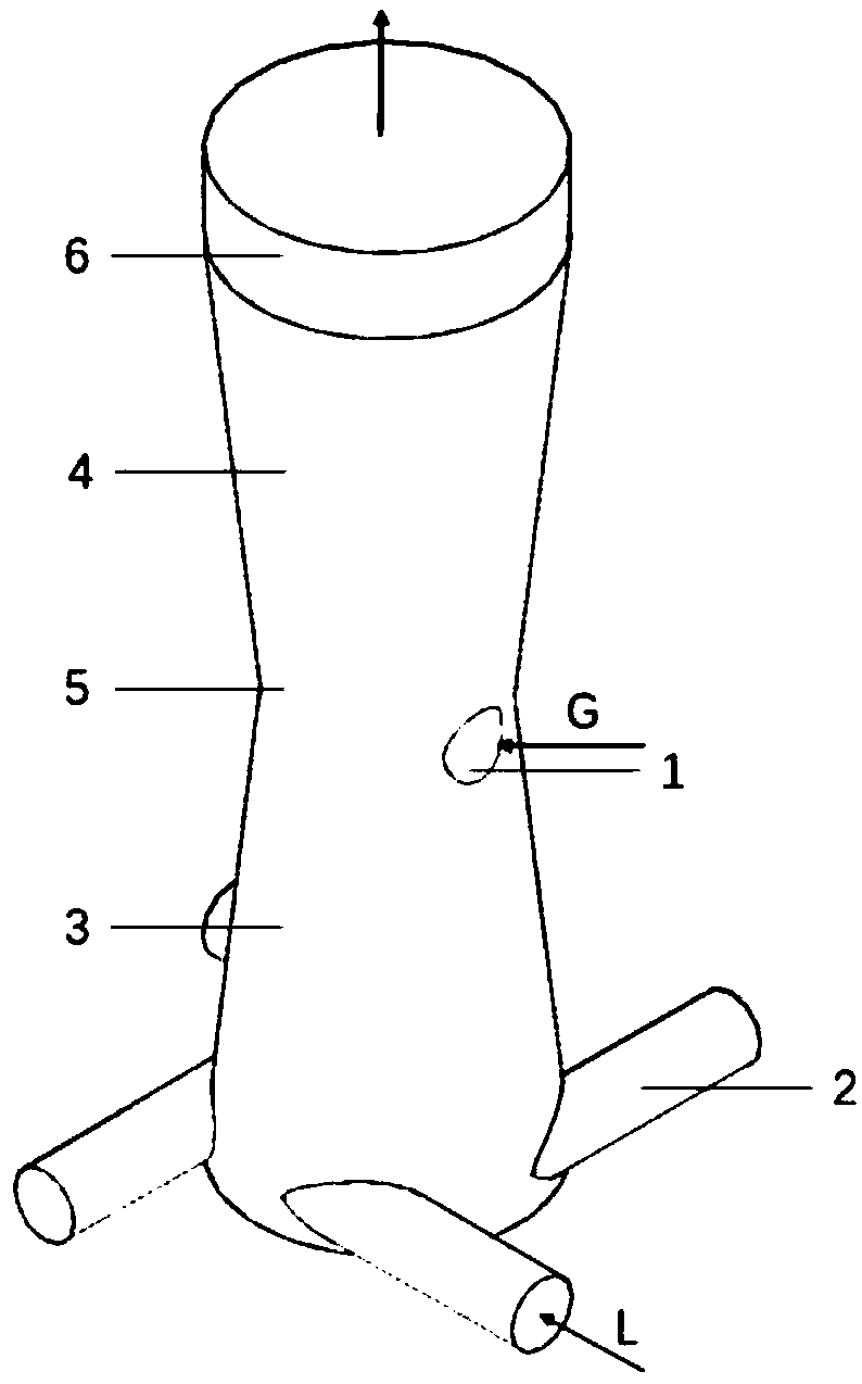
[0036] use as figure 2 The microbubble generator shown includes an air inlet 1 , a liquid inlet pipe 2 , a venturi structure tapering section 3 , an expander pipe 4 , and a throat pipe 5 . The total length of the microbubble generator is 95mm, of which the bottom of the tapering section is closed, the length of the tapering section and the expanding section are both 40mm, the length of the throat is 0mm, and the length of the developing section is 15mm. The diameter of the outlet of the diverging section is equal to the diameter of the bottom of the tapering section, both of which are 26mm. A circular air inlet with a diameter of 6mm, four tangential liquid inlet pipes with a diameter of 6mm and a length of 25mm.

[0037] Taking the air-water system as an example, a high-speed camera is used to measure the size and distribution of the bubbles generated by the microbubble generator. Air velocity at the air inlet u g =0.24m / s, the liquid velocity at the throat increases from t...

Embodiment 3

[0039] The only difference from Example 1 is that the gas velocity u at the air inlet g =0.36m / s, use a high-speed camera to shoot the bubbles generated by the microbubble generator, when the liquid velocity at the throat u l =1.60m / s, microbubble fraction η=64%.


PUM


Abstract

The invention discloses a micro-bubble generator and gas-liquid reactor comprising same. The micro-bubble generator is composed of a liquid inlet pipe, a gas inlet hole and a Venturi pipe. The Venturipipe at least includes, successively from bottom to top, a shrinking portion with sealed bottom, a throat tube portion and an expanding portion, wherein the liquid inlet pipe is located at the bottomof the shrinking portion of the Venturi pipe and the gas inlet hole is formed in the throat tube portion. The micro-bubble generator has compact structure, is low in energy consumption, is good in micro-bubble generation effect and is convenient to maintain. By using the micro-bubble generator, the gas-liquid reactor is greatly improved in gas-liquid mass transfer efficiency.

Description

technical field [0001] The invention relates to the field of petrochemical industry, in particular to a gas-liquid reactor comprising a novel microbubble generator. Background technique [0002] Microbubbles have the characteristics of large specific surface area, high gas holdup, slow rising speed and fast dissolution speed. They are an important means to enhance mass transfer and are widely used in the mass transfer process between gas-liquid two phases in the petrochemical industry and wastewater treatment. , Brewing and aerobic biological farming and other fields. At present, the occurrence of microbubbles is mainly realized by microbubble generators, and the generation methods are mainly divided into the following types: (1) shearing and breaking into bubbles, such as Venturi type microbubble generators; (2) depressurization or heating to form bubbles , such as pressure-dissolving microbubble generators; (3) ultrasonic bubble formation; (4) microporous bubble formation...

Claims


Application Information

Patent Timeline
Patent Type & Authority Applications(China)
IPC IPC(8): B01F5/04B01J10/00B01J19/24
CPCB01J10/00B01J19/0053B01J19/24B01F25/3125B01F25/312
Inventor 黄正梁王欣妍帅云孙婧元郭晓云张池金盛涛杨遥廖祖维王靖岱阳永荣蒋斌波张浩淼杨勇
Owner ZHEJIANG UNIV
Why Eureka
Try Eureka