Waterproof sealing assembly for horizontal through-wall pipeline and leakage detection method of waterproof sealing assembly

A technology of waterproof sealing and detection method, which is applied to pipeline systems, pipes/pipe joints/fittings, pipes, etc., and can solve the problems of inability to detect whether waterproof casings and wall-penetrating pipes are leaking, and inconvenient handling

Active Publication Date: 2021-04-13
淮安市博彦土木工程科学研究院有限公司
View PDF7 Cites 4 Cited by
  • Summary
  • Abstract
  • Description
  • Claims
  • Application Information

AI Technical Summary

Problems solved by technology

[0004] The purpose of the present invention is to provide a waterproof sealing assembly for horizontal wall-pipelines and its leakage detection method, which can effectively solve th

Method used


Image

  • Waterproof sealing assembly for horizontal through-wall pipeline and leakage detection method of waterproof sealing assembly
  • Waterproof sealing assembly for horizontal through-wall pipeline and leakage detection method of waterproof sealing assembly
  • Waterproof sealing assembly for horizontal through-wall pipeline and leakage detection method of waterproof sealing assembly

Examples


Embodiment 1

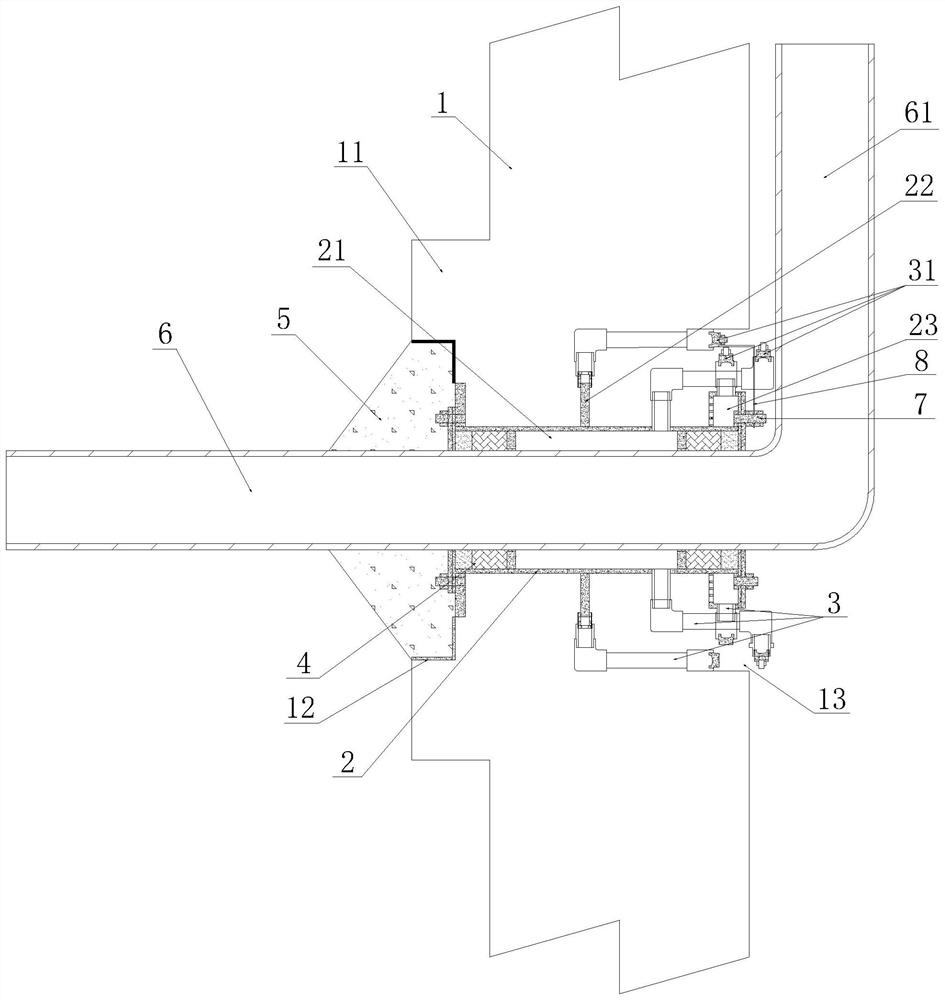
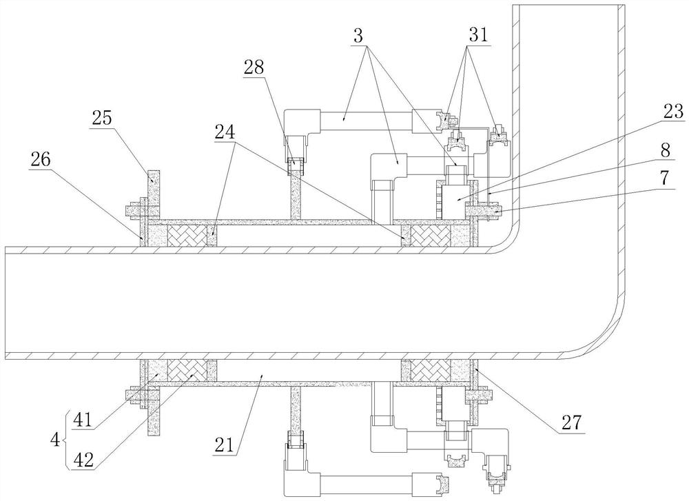
[0027] The technical scheme that the present invention takes can refer to figure 1 and figure 2As shown, a waterproof sealing assembly for a horizontal wall-penetrating pipeline is used to seal the horizontal wall-penetrating pipeline 6 passing through the wall. Ring 22, the waterproof casing 2 is set outside the wall-penetrating pipe 6 located in the wall 1, the inner wall of the waterproof casing 2 is provided with an inner retaining ring 24 near the two ends, and the two ends of the outer wall of the waterproof casing 2 are outwards. An outer retaining ring 25 is provided, and the waterproof casing 2 is near the inner wall surface of the wall body 1 (refer to figure 1 , in this example the figure 1 The wall on the right side is defined as the inner wall) The outer retaining ring 25 is provided with an inner wall wing 27, and the waterproof casing 2 is near the outer wall of the wall 1 (refer to figure 1 , in this example the figure 1 The wall on the left side is define...

Embodiment 2

[0029] refer to Figure 1~3 In this embodiment, on the basis of Embodiment 1, an annular water storage tank is provided outside the waterproof casing 2 at the 4 places of the sealing member, and the side of the water storage tank near the inner wall surface of the wall body 1 is open, and the inner wall The wing plate 27 is arranged at the open end of the water storage tank, is closely combined with the water storage tank and forms an airtight water storage chamber 23 in the tank; the outer wall of the water storage chamber 23 is provided with a leak detection tube 3 communicated with the water storage chamber 23 to detect leaks. One end of the pipe 3 is connected to the outer wall of the water storage tank, and the other end is connected to the high-pressure water pump 9 or the grouting pump; If water leakage is judged, disconnect the connection with the high-pressure water pump, connect the leak detection pipe to the grouting pump, and grout the water storage chamber through...

Embodiment 3

[0031] refer to Figure 1~3 In this embodiment, on the basis of Embodiment 2, an annular housing chamber 28 is provided on the outer ring of the water stop ring 22, and a leak detection tube 3 communicating with the housing chamber 28 is provided on the outer ring of the housing chamber 28. One end of the leakage pipe 3 is connected to the outer wall of the accommodation chamber 28, and the other end is connected to the high-pressure water pump 9 or the grouting pump; If it is judged that there is leakage, disconnect the connection with the high-pressure water pump, connect the leak detection pipe to the grouting pump, and grout the chamber through the leak detection pipe to deal with the leakage; if it is judged that there is no leakage, disconnect the connection with the grouting pump There is no need to deal with the connection of the high-pressure water pump, but for the sake of insurance, a grouting pump can also be connected to fill the cavity and the leak detection pipe...


PUM


Abstract

The invention relates to a waterproof sealing assembly for a horizontal through-wall pipeline. The waterproof sealing assembly comprises a waterproof casing pipe and a water stop ring, wherein the waterproof casing pipe is arranged outside the through-wall pipeline pipeline in a sleeving mode, an inner check ring is arranged on the inner wall of the waterproof casing pipe, outer check rings are arranged at the two ends of the outer wall of the waterproof casing pipe outwards, inner wall wing plates are arranged at the positions, close to the inner wall surface of a wall, of the outer check rings, outer wall wing plates are arranged at the outer check rings, close to the outer wall surface of the wall, of the waterproof casing pipe, cavities are formed between the inner wall wing plates and the inner check rings on the same side and between the outer wall wing plates and the inner check rings on the same side, and sealing pieces are arranged in the cavities; and a cavity is formed between the inner wall of the waterproof casing pipe between the two inner check rings and the outer wall of the through-wall pipeline, a leakage detecting pipe communicating with the cavity is arranged on the outer wall of the waterproof casing pipe, one end of the leakage detecting pipe is connected with the outer wall of the waterproof casing pipe, and the other end of the leakage detecting pipe is connected with a high-pressure water pump or a grouting pump. In addition, the invention further relates to a leakage detection method of the waterproof sealing assembly. The problems that in the prior art, whether leakage exists in a cavity formed between the waterproof casing pipe and the through-wall pipeline or not cannot be detected, and treatment is inconvenient after leakage occurs can be effectively solved.

Description

technical field [0001] The invention relates to the technical field of building waterproof casings, in particular to a waterproof sealing assembly for horizontal wall-penetrating pipelines and a leakage detection method thereof. Background technique [0002] With the rapid development of social economy and the continuous increase of urban population, the use space of urban buildings has been further expanded. In terms of building design, pipelines are often concentrated, so that pipelines need to pass directly through floors, roofs or walls. In this case, the installation of waterproof casing is the most critical technology to ensure the quality of drainage engineering. [0003] Waterproof casing is a kind of wall-penetrating pipe for pipelines. According to different structural forms, waterproof casing can be divided into three types: flexible waterproof casing, rigid waterproof casing and rigid waterproof wing ring. For rigid waterproof casing, it is often used on basemen...

Claims


Application Information

Patent Timeline
IPC IPC(8): F16L5/02F17D5/02
CPCF16L5/02F17D5/02
Inventor 陈胜陈辉
Owner 淮安市博彦土木工程科学研究院有限公司
Why Eureka
Try Eureka