Multilayer grating structure
A technology of grating structure and grating layer, applied in the direction of diffraction grating, optics, optical elements, etc., can solve the problem of uneven diffraction efficiency of grating structure
- Summary
- Abstract
- Description
- Claims
- Application Information
AI Technical Summary
Problems solved by technology
Method used
Image

Examples
Embodiment 1
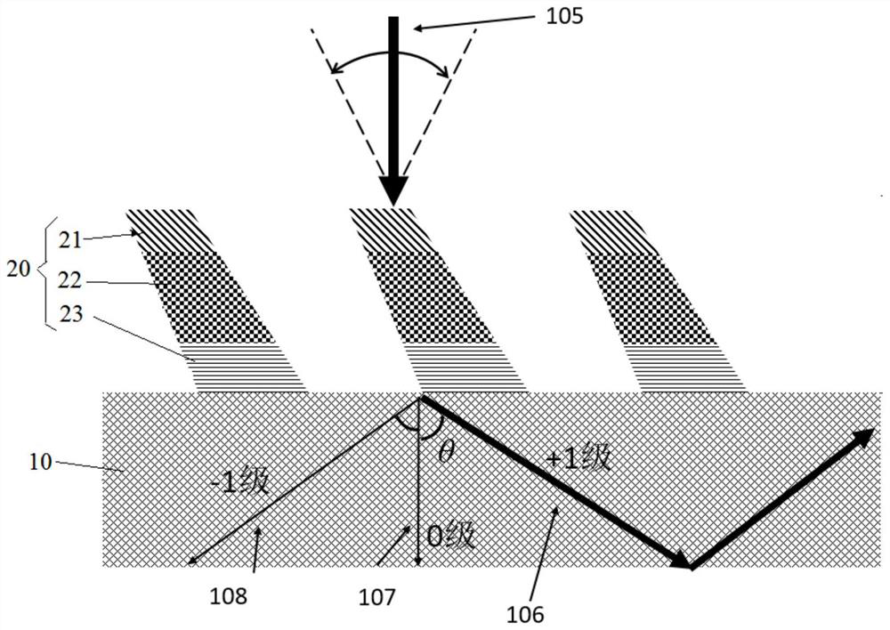
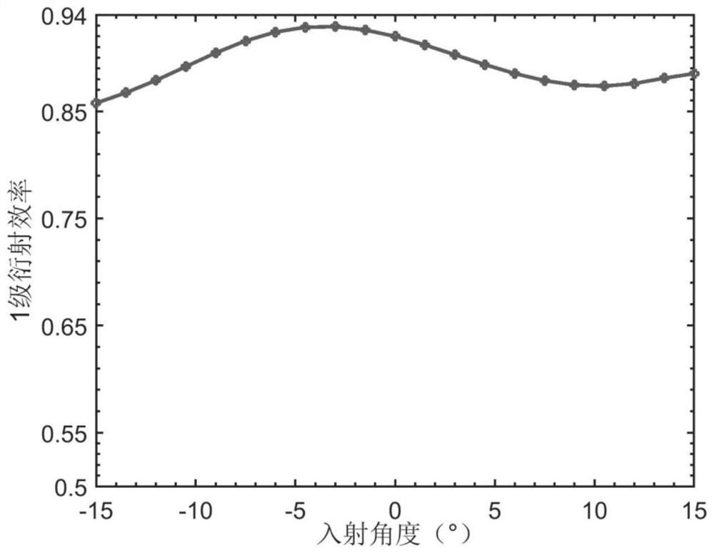
[0037] exist figure 1 In the specific embodiment shown, among the grating layers of the grating structure 20 along the direction perpendicular to the base structure 10, the grating layer away from the base structure 10 is the first grating layer 21, and the grating layer connected to the first grating layer 21 is the second grating layer. The grating layer 22 , the refractive index of the first grating layer 21 is smaller than the refractive index of the second grating layer 22 . This setting can reduce the difference in refractive index between the grating structure 20 and the incident medium, reduce the sudden change in the refractive index between the incident medium and the grating structure 20, can effectively improve the transmission efficiency of the grating structure 20, and can also effectively improve the angle bandwidth and efficiency.
[0038] It should be noted that, in the existing single-layer grating, when the light enters the grating from the incident medium,...
Embodiment 2
[0054] The difference from the first embodiment is that the grating structure 20 has only two grating layers, and there are residual layers between the grating structure 20 and the base structure 10 .
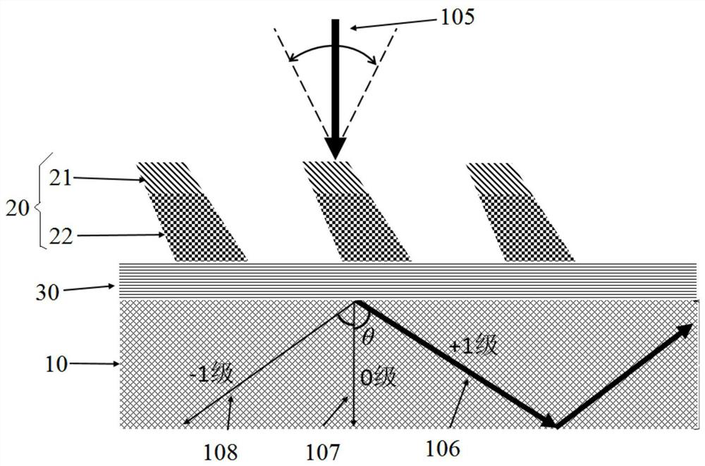
[0055] exist image 3 In the specific embodiment shown, the grating layer only has a first grating layer 21 and a second grating layer 22, and the second grating layer 22 is a functional layer with the highest refractive index among the multi-layer grating layers.
[0056] exist image 3 In the specific embodiment shown, the multilayer grating structure further includes a residual layer 30 disposed between the base structure 10 and the grating structure 20 . The residual layer 30 may be a residual adhesive layer in the nanoimprinting process, or a residual layer may be separately produced by using deposition technology, coating technology, or spraying technology. Although the residual layer is difficult to eliminate in the process, the residual layer will not reduce the perfo...
Embodiment 3
[0058] The difference from the first embodiment is that there is a residual layer 30 in this embodiment.
[0059] exist Figure 4 In the specific embodiment shown, the multilayer grating structure further includes a residual layer 30 disposed between the base structure 10 and the grating structure 20 . The residual layer 30 may be a residual adhesive layer in the nanoimprinting process, or a residual layer may be separately produced by using deposition technology, coating technology, or spraying technology. Although the residual layer is difficult to eliminate in the process, the residual layer will not reduce the performance of the grating structure 20 , but will also improve the performance of the grating structure 20 to a certain extent.
PUM
| Property | Measurement | Unit |
|---|---|---|
| Depth | aaaaa | aaaaa |
| Depth | aaaaa | aaaaa |
Abstract
Description
Claims
Application Information
 - R&D
- Intellectual Property
- Life Sciences
- Materials
- Tech Scout
- Unparalleled Data Quality
- Higher Quality Content
- 60% Fewer Hallucinations
Browse by: Latest US Patents, China's latest patents, Technical Efficacy Thesaurus, Application Domain, Technology Topic, Popular Technical Reports.
© 2025 PatSnap. All rights reserved.Legal|Privacy policy|Modern Slavery Act Transparency Statement|Sitemap|About US| Contact US: help@patsnap.com