
Yaw angle-based groove type structure surface drag reduction effect prediction method

A technology of structural surface and prediction method, applied in special data processing applications, instruments, electrical digital data processing, etc., can solve problems such as low applicability and robustness, and achieve the effect of improving computing efficiency

Active Publication Date: 2021-04-13
BEIJING INSTITUTE OF TECHNOLOGYGY
View PDF2 Cites 1 Cited by
  • Summary
  • Abstract
  • Description
  • Claims
  • Application Information

AI Technical Summary

Problems solved by technology

[0009] The purpose of the present invention is to overcome the defects of the prior art, for the technical problem of low applicability and low robustness in the prediction of the drag reduction effect in the design of the surface of the groove structure, and creatively propose a yaw angle-based groove Prediction method of surface drag reduction effect of trough structure

Method used


Image

  • Yaw angle-based groove type structure surface drag reduction effect prediction method
  • Yaw angle-based groove type structure surface drag reduction effect prediction method
  • Yaw angle-based groove type structure surface drag reduction effect prediction method

Examples


Embodiment

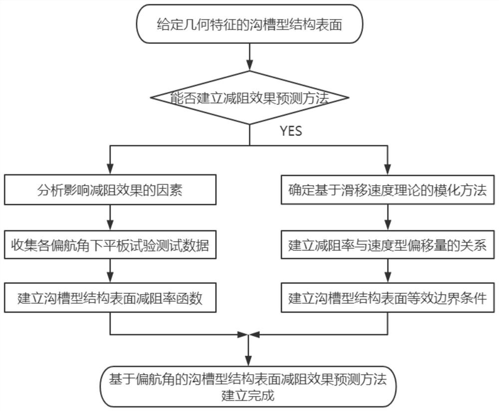
[0058] A method for predicting the surface drag reduction effect of grooved structures based on yaw angle, comprising the following steps:

[0059] S1`: Clarify the flow control mechanism and time-averaged flow characteristics of the grooved structure surface treatment technology.

[0060] In this embodiment, the groove structure is a symmetrical V-shaped groove surface on a micron scale, such as Figure 4 shown. Because its flow control mechanism and time-averaged flow characteristics are consistent with the surface treatment technology of the groove structure, the drag reduction effect can be predicted.

[0061] S2`: Determine the idea of ​​numerical modeling processing.

[0062] First, establish the relationship between the drag reduction effect and the influencing factors under the influence of yaw angle;


PUM


Abstract

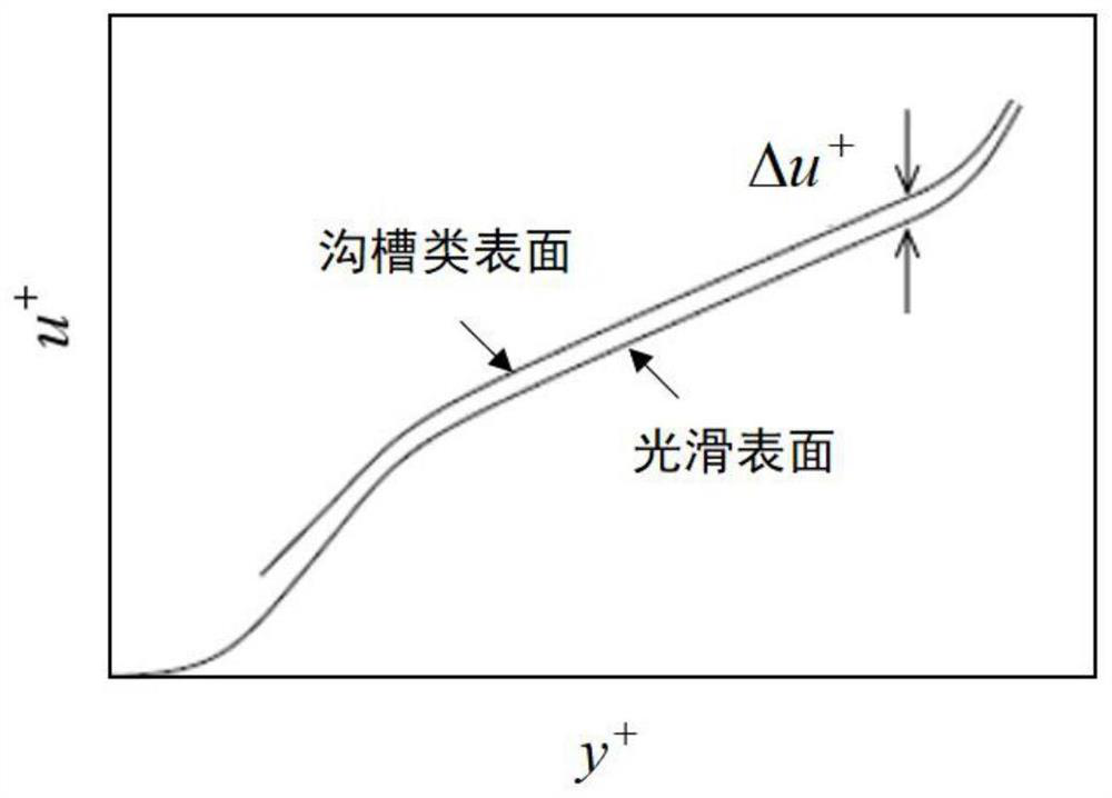
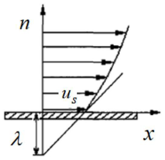
The invention discloses a yaw angle-based groove type structure surface drag reduction effect prediction method, and belongs to the technical field of aerodynamics. According to the method, the design thought of the drag reduction effect prediction technology is determined according to the flow control mechanism of surface treatment of the groove type structure and the influence of the flow control mechanism on the time-average flow characteristic of the boundary layer. By selecting the specific structural form of the surface of the groove type structure and combining the test (or numerical value) test data of the surface of the flat plate, the function relationship between the drag reduction effect under the influence of the yaw angle and the influence factors is established. The relationship between the drag reduction effect and the CFD modeling parameter is established by using the slip speed theory. A flow field on the surface of the groove type structure on the smooth surface is simulated by means of a modeled CFD program. Compared with the prior art, the method has the advantages that the prediction efficiency of the surface drag reduction effect of the groove-shaped structure can be improved, meanwhile, the action effect under the influence of the yaw angle is accurately predicted, and the method is widely suitable for surface drag reduction design work of the groove-shaped structure of an industrial product in a complex flowing environment.

Description

technical field [0001] The invention relates to a method for predicting the surface drag reduction effect of a grooved structure, in particular to a method for predicting the surface drag reduction effect of a grooved structure based on a yaw angle, and belongs to the technical field of aerodynamics. Background technique [0002] The surface treatment technology of groove structure is a turbulent drag reduction technology based on bionic design, which was proposed in the 1980s. This technology uses the micro-scale groove structure processed on the smooth surface. On the one hand, by controlling the wall turbulent quasi-order structure, it can limit the burst of near-wall turbulence and suppress the momentum exchange of the boundary layer; on the other hand, by storing low-energy fluid, Increase the thickness of the viscous sublayer to achieve drag reduction in the turbulent boundary layer. [0003] Because the groove structure surface treatment technology has the characteri...

Claims


Application Information

Patent Timeline
Patent Type & Authority Applications(China)
IPC IPC(8): G06F30/28G06F30/17G06F113/08G06F119/14
CPCG06F30/28G06F30/17G06F2113/08G06F2119/14
Inventor 马启新刘艳明
Owner BEIJING INSTITUTE OF TECHNOLOGYGY
Learn More