Dismounting device for current transformer of 10-kilovolt switch cabinet

A current transformer and switchgear technology, applied in the computer field, can solve problems such as low work efficiency, personal injury, and difficulty in exerting force, and achieve the effect of reducing the number of workers, reducing the length of working time, and reducing the complexity of disassembly and assembly

Pending Publication Date: 2021-04-13
JINCHENG POWER SUPPLY COMPANY OF STATE GRID SHANXI ELECTRIC POWER
View PDF8 Cites 0 Cited by
  • Summary
  • Abstract
  • Description
  • Claims
  • Application Information

AI Technical Summary

Problems solved by technology

[0002] At present, in order to ensure the safe and reliable operation of the power system and reduce the power outage time of residents, it is necessary to replace the current transformer with small transformation ratio and small capacity in the 10kV indoor switchgear with a current transformer with large transformation ratio and large capacity. The inner space is narrow, and it is very difficult to adjust, replace and assemble electrical equipment during the daily maintenance of the switchgear
When disassembling and assembling heavy current transformers, 4 to 5 workers are required, two of them work together to support the current transformer inside and outside the switch cabinet, and the third worker uses rope-bound Pull the current transformer in the same way, and the fourth worker leans over and squeezes into the cabinet to dismantle / install the screws with 4 fixing bolts to dismantle / install the current transformer; During the disassembly / installation process of the device, the whole process should be lifted, and the force should not be unloaded.
Moreover, it is difficult to pull the current transformer by means of rope binding, and once the current transformer slips off the rope, it will cause personal injury
[0003] The disassembly and assembly process of the above-mentioned current transformer has the defects of long operation time and low work efficiency

Method used


Image

  • Dismounting device for current transformer of 10-kilovolt switch cabinet
  • Dismounting device for current transformer of 10-kilovolt switch cabinet
  • Dismounting device for current transformer of 10-kilovolt switch cabinet

Examples


Embodiment

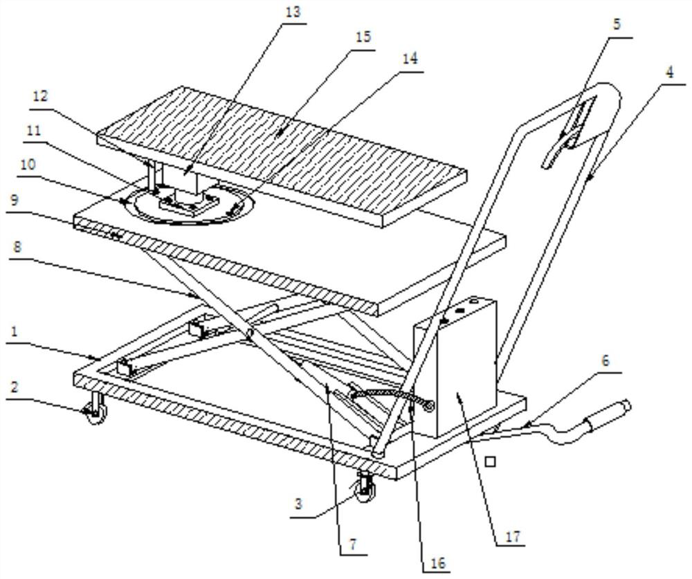
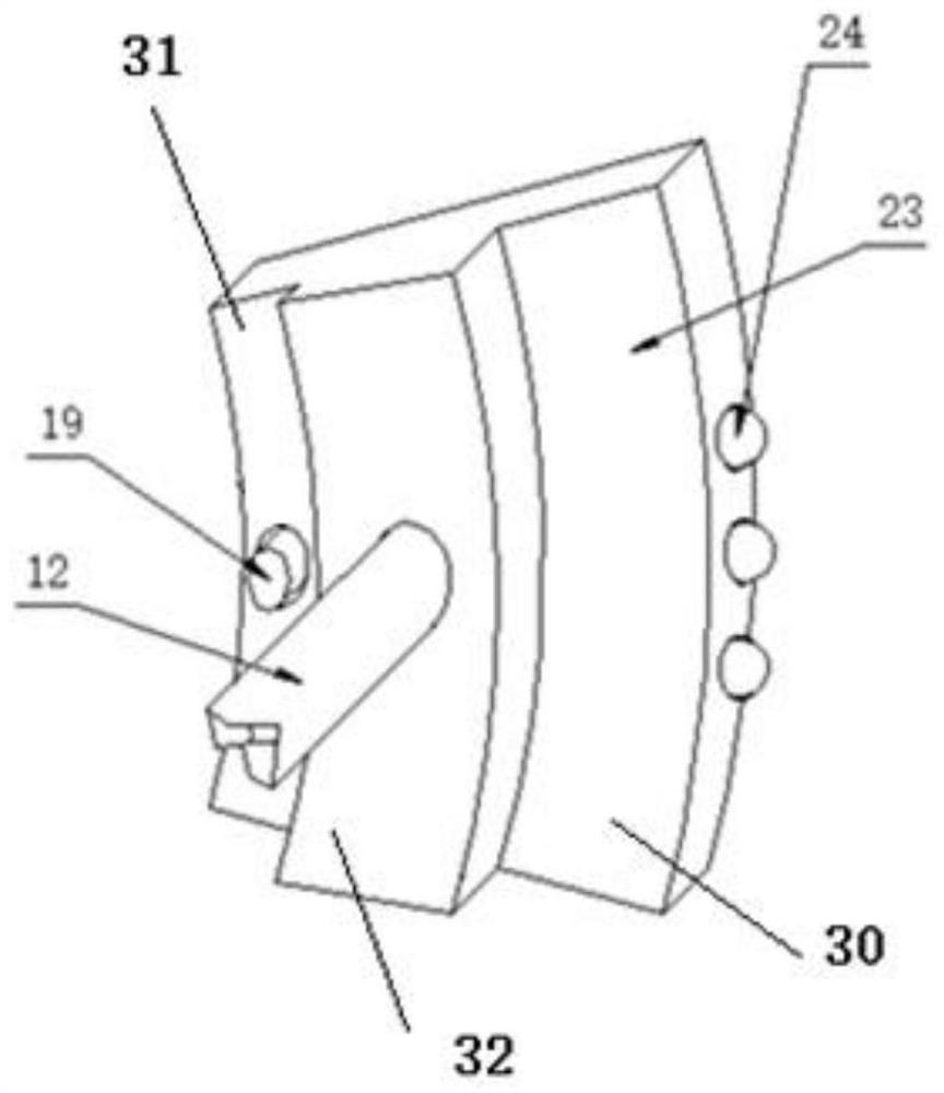
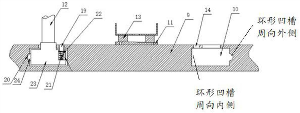
[0031] see figure 1 A structural schematic diagram of a disassembly device for a 10 kV switch cabinet current transformer shown, the disassembly device for a 10 kV switch cabinet current transformer includes: a base 1, a directional caster 2, a movable caster 3, a push Handle 4, foot booster lever 6, hydraulic lever 7, lifting frame 8, fixed plate 9, fixed seat 11, limit lever 12, rotating bearing 13, support plate 15, connecting pipe 16, electric operation box 17, slider 23, and positioning block 19.

[0032] The push handle is installed on one side of the surface of the base, and the angle between the installed push handle and the bottom plate is greater than 90 degrees.

[0033] Therefore, in one embodiment, the push handle can be obliquely installed on one side of the surface of the base.

[0034] The moving casters are installed on the bottom surface of the base near the pushing handle; the directional casters are installed on the bottom surface of the base away from th...


PUM


Abstract

The invention provides a dismounting device for a current transformer of a 10-kilovolt switch cabinet. A rotating bearing is arranged on a fixed plate, and a support plate for fixing the position of the current transformer or placing the current transformer is fixed at the top of the rotating bearing; therefore, when the current transformers located at different positions in the 10-kilovolt switch cabinet need to be disassembled and assembled, the supporting plate can be driven by the rotating bearing to rotate in the plane where the supporting plate is located, and the supporting plate is rotated to the position of the current transformer needing to be disassembled and assembled; the current transformer to be disassembled is fixed or the current transformer to be installed is placed at the installation position of the current transformer, the number of workers needed for disassembling and assembling the current transformer can be greatly reduced, the disassembling and assembling complexity of the current transformer is lowered, and the operation time length of the current transformer is shortened.

Description

technical field [0001] The invention relates to the field of computer technology, in particular to a disassembly and assembly device for a current transformer of a 10 kV switch cabinet. Background technique [0002] At present, in order to ensure the safe and reliable operation of the power system and reduce the power outage time of residents, it is necessary to replace the current transformer with small transformation ratio and small capacity in the 10kV indoor switchgear with a current transformer with large transformation ratio and large capacity. The inner space is narrow, and it is very difficult to adjust, replace and assemble electrical equipment during the daily maintenance of the switchgear. When disassembling and assembling heavy current transformers, 4 to 5 workers are required, two of them work together to support the current transformer inside and outside the switch cabinet, and the third worker uses rope-bound Pull the current transformer in the same way, and ...

Claims


Application Information

Patent Timeline
Patent Type & Authority Applications(China)
IPC IPC(8): H02B3/00
CPCH02B3/00
Inventor 李靖宇裴常卓姬鹏飞牛玉琨卫兴胜李海波郭九宏王斌红王园园卫斌郭思宇冯波波庄嵩岩
Owner JINCHENG POWER SUPPLY COMPANY OF STATE GRID SHANXI ELECTRIC POWER
Why Eureka
Try Eureka