
Surgical retractor for heart transplantation and using method thereof

A technology for surgical retractors and heart transplantation, which is applied in the field of medical devices, can solve the problems of no wound opening, adjustment, retractor detachment, etc., and achieve the effects of improving stability, reducing manpower burden, and facilitating surgical operations

Active Publication Date: 2021-04-16
XIEHE HOSPITAL ATTACHED TO TONGJI MEDICAL COLLEGE HUAZHONG SCI & TECH UNIV
View PDF9 Cites 0 Cited by
  • Summary
  • Abstract
  • Description
  • Claims
  • Application Information

AI Technical Summary

Problems solved by technology

[0005] The purpose of the present invention is to provide a surgical retractor for heart transplantation and its use method to solve the problem that the existing surgical retractor cannot be adjusted according to the thickness of the patient's skin and fat, and the retractor is prone to detachment during heart transplantation without an auxiliary mechanism. The surgical wound is stretched, and the degree of stretching of the surgical opening cannot be fine-tuned to facilitate the operation
[0007] In order to realize the above-mentioned surgical retractor for heart transplantation and its use method, the existing surgical retractor cannot be adjusted according to the thickness of the patient's skin and fat, and the retractor is prone to detachment during heart transplantation. The opening of the surgical opening cannot be fine-tuned to facilitate surgical operation. The present invention provides the following technical solutions:

Method used


Image

  • Surgical retractor for heart transplantation and using method thereof
  • Surgical retractor for heart transplantation and using method thereof
  • Surgical retractor for heart transplantation and using method thereof

Examples


Embodiment Construction

[0029] The following will clearly and completely describe the technical solutions in the embodiments of the present invention with reference to the accompanying drawings in the embodiments of the present invention. Obviously, the described embodiments are only some, not all, embodiments of the present invention. Based on the embodiments of the present invention, all other embodiments obtained by persons of ordinary skill in the art without creative efforts fall within the protection scope of the present invention.

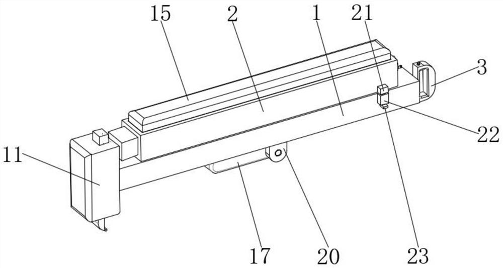
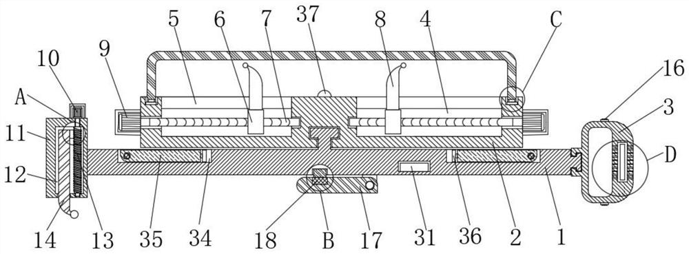
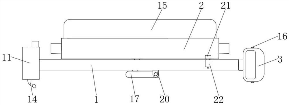
[0030] see Figure 1 to Figure 8 , the present invention provides a technical solution: a surgical retractor for heart transplantation, comprising a retractor rod 1, the surface of the retractor rod 1 is clamped with a retractor box 2, one end of the retractor rod 1 is fixedly connected with an adjustment box 11, and the adjustment box 11 There is a storage room 12 inside, the inner cavity of the storage room 12 is movably sleeved with a second screw 13, the top of...


PUM


Abstract

The invention discloses a surgical retractor for heart transplantation and a using method thereof, and relates to the technical field of medical instruments, in particular to a surgical retractor for heart transplantation. Thesurgical retractor comprises a retractor rod, a retractor box is clamped on the surface of the retractor rod, an adjusting box is fixedly connected to one end of the retractor rod, and a storage chamber is formed in the adjusting box. And a second lead screw is movably connected to an inner cavity of the storage chamber in a sleeving mode, and a second servo motor is fixedly mounted at the top of the adjusting box. According to the operation retractor for heart transplantation, through cooperative use of an adjusting box, a second lead screw, a first retractor body and a tooth-shaped connecting block, in the heart transplantation operation process, the thickness of the skin and fat of the thoracic cavity of a patient is observed firstly, and then the second servo motor is started to drive the second lead screw to rotate; and a first retractor is driven to move up and down through meshing transmission of the second lead screw and the tooth-shaped connecting block, the function of adjusting the length of the first retractor is achieved, and the stability of the surgical retractor for heart transplantation is improved.

Description

technical field [0001] The invention relates to the technical field of medical instruments, in particular to a surgical retractor for heart transplantation and a method for using the same. Background technique [0002] Heart transplantation is mainly a surgical transplantation for advanced severe heart disease. During heart transplantation, the patient's chest cavity needs to be cut open, and the cut skin and fat are pulled apart by retractors so that doctors can operate on the heart. [0003] The Chinese invention patent with application number 201310169214.7 discloses a surgical retractor, which is composed of composite hook teeth, a slat handle and a reel handle. The composite hook teeth are arranged on the upper end of the slat handle, and the reel handle is arranged on The lower end of the slatted handle, the lower end of the slatted handle is connected with the reel handle in an inverted T shape. The compound hook teeth are composed of a row of teeth and a single tooth...

Claims


Application Information

Patent Timeline
IPC IPC(8): A61B17/02
Inventor 董念国尚小珂
Owner XIEHE HOSPITAL ATTACHED TO TONGJI MEDICAL COLLEGE HUAZHONG SCI & TECH UNIV
Learn More