

Cutting equipment for machining mechanical parts
A technology for cutting equipment and mechanical parts, used in metal processing equipment, metal processing mechanical parts, manufacturing tools, etc., can solve problems such as unfavorable use, inability to fix well, and inability to adjust mechanical parts, and achieve the effect of enhancing shock resistance
- Summary
- Abstract
- Description
- Claims
- Application Information
AI Technical Summary
Problems solved by technology
Method used
Image

Examples
Embodiment
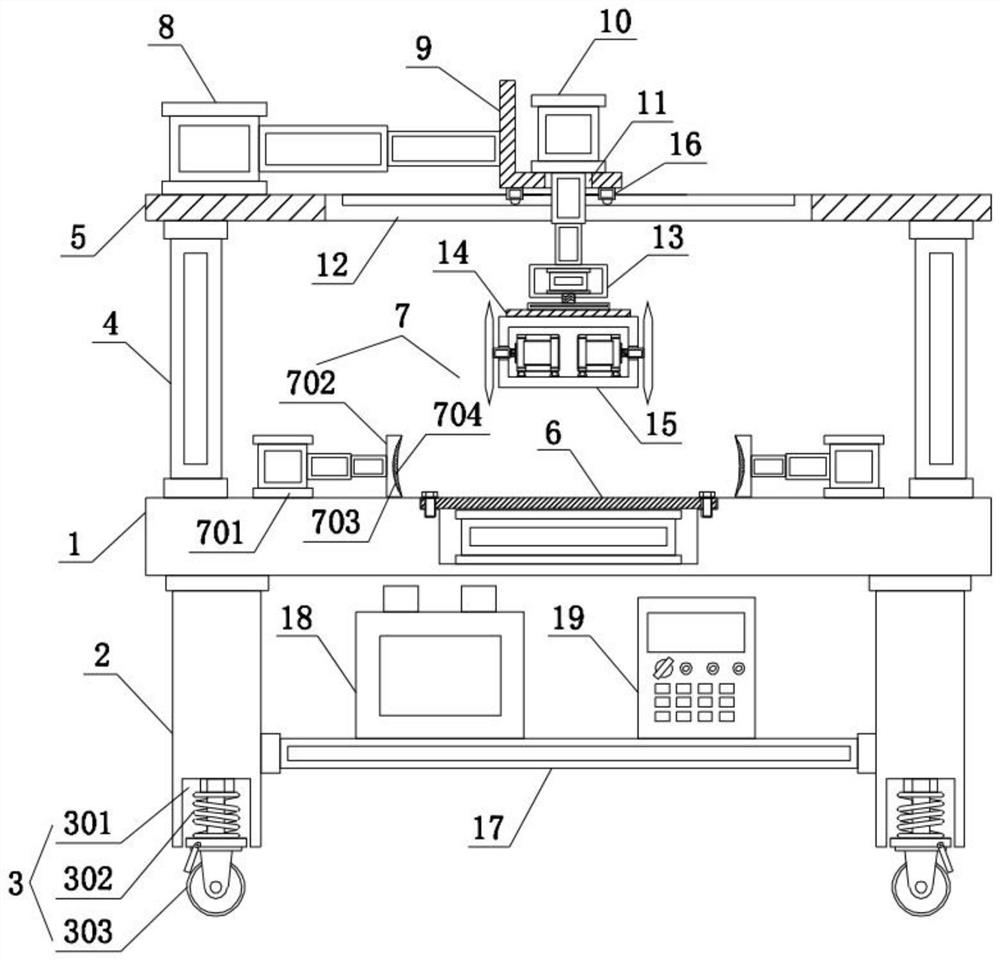
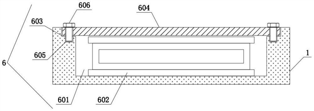
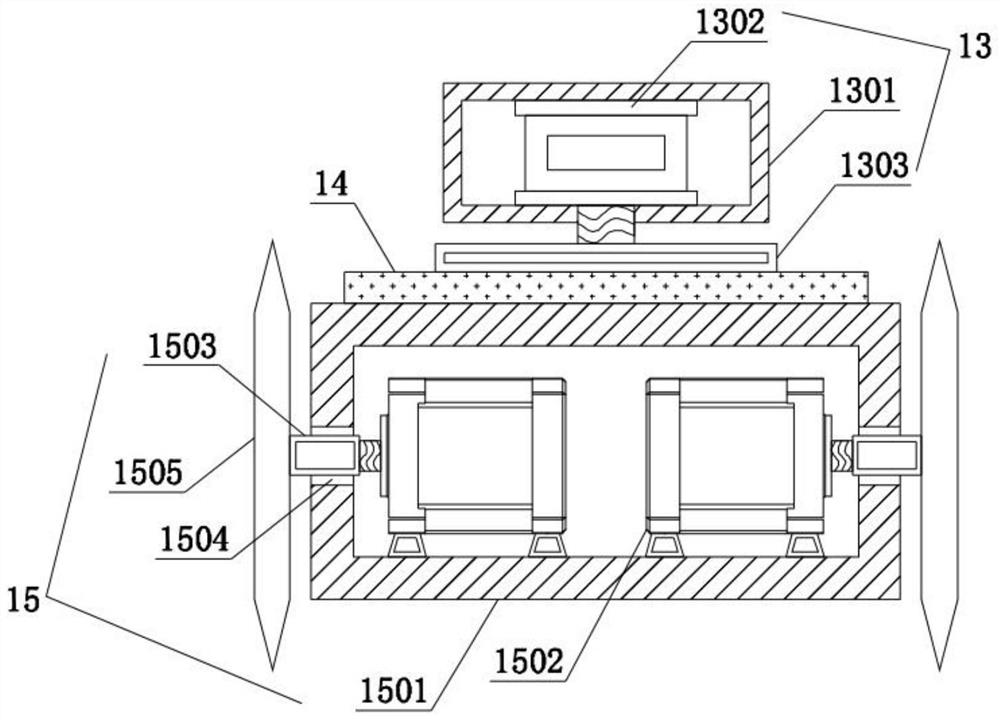
[0031] see Figure 1-5 , a cutting device for processing mechanical parts, comprising a workbench 1, legs 2 are fixedly connected to the four corners of the bottom of the workbench 1, and a moving mechanism 3 is fixedly installed on the bottom of the legs 2. The four corners of the top of the workbench 1 are fixedly connected with uprights 4, and the tops of the uprights 4 are fixedly connected with a top plate 5, and the top of the workbench 1 is fixedly equipped with an adsorption mechanism 6. The workbench 1 The top of the top plate is located on the left and right sides of the adsorption mechanism 6, and the limit mechanism 7 is fixedly installed. The left side of the top of the top plate 5 is fixedly installed with the first telescopic cylinder 8, and the output end of the first telescopic cylinder 8 is fixedly connected with an L-shaped plate 9, the top of the L-shaped plate 9 is fixedly equipped with a second telescopic cylinder 10, the top of the L-shaped plate 9 is pr...
PUM
 Abstract
Description
Claims
Application Information