Frozen tuna unloading assistor
An auxiliary, tuna technology, applied in the directions of loading/unloading, transportation and packaging, climate change adaptation, etc., can solve problems such as danger and tuna crushing, and achieve the effect of avoiding operation failure, avoiding freezing damage, and expanding the clamping range.
- Summary
- Abstract
- Description
- Claims
- Application Information
AI Technical Summary
Problems solved by technology
Method used
Image
Examples
Embodiment 1
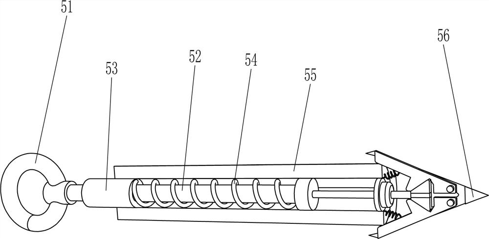
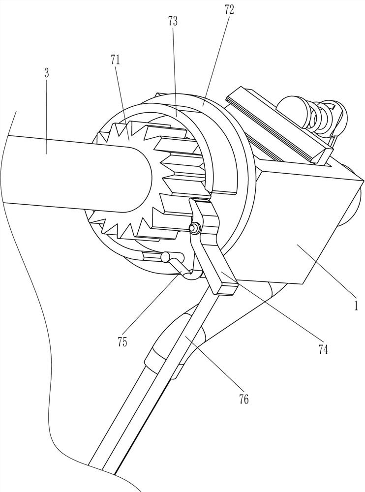
[0064] A frozen tuna unloading aid such as figure 1 As shown, it includes an N-shaped plate 1, a fixed shaft 2, a rotating tube 3, a wire take-up mechanism 4, a snap-in mechanism 5, a fixing mechanism 6 and a locking mechanism 7. The N-shaped plate 1 is equipped with a fixing mechanism 6, and the N-shaped A fixed shaft 2 is connected between the plates 1, and the right side of the fixed shaft 2 is connected with a rotating pipe 3 in a rotational manner. A locking mechanism 7 is connected between the rotating tube 3 and the N-shaped plate 1 on the right.
[0065] When people need to unload the tuna, first fix the N-shaped plate 1 on the carriage, turn the fixing mechanism 6 to fix the N-shaped plate 1, and people pull the parts of the locking mechanism 7, and then pull the locking mechanism 5 to move the locking mechanism backward. Into the tuna, drive the parts of the take-up mechanism 4 to rotate, and then make the rotating tube 3 and the parts of the locking mechanism 7 rot...
Embodiment 2
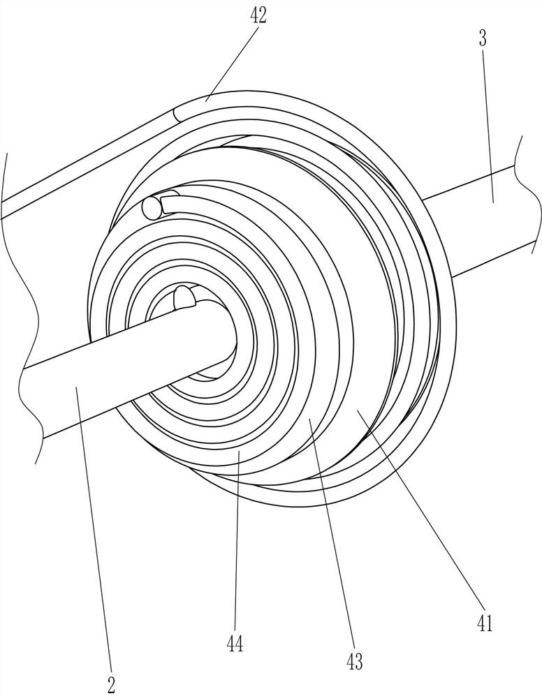
[0067] On the basis of Example 1, such as Figure 2-4 As shown, the take-up mechanism 4 includes a reel 41, a first pull cord 42, a driving disc 43 and a mainspring 44, the left side of the rotating tube 3 is connected with a reel 41, and the reel 41 is wound with a first pulley. Rope 42, the end of the first pull cord 42 is connected to the snap-in mechanism 5, the left side of the rotating tube 3 is connected to the driving disc 43, the driving disc 43 is located on the left side of the winding wheel 41, between the left side of the driving disc 43 and the middle part of the fixed shaft 2 A mainspring 44 is connected.
[0068]When people move the snap-in mechanism 5 backwards, the reel 41 is driven to rotate and the first stay cord 42 is loosened, and the rotating tube 3 and the driving disc 43 are driven to rotate at the same time, the mainspring 44 is twisted, and the snap-in mechanism 5 is snapped into the tuna. Finally, by toggling the locking mechanism 7, under the act...
Embodiment 3
[0072] On the basis of Example 2, such as Figure 5-8 As shown, the fixing mechanism 6 includes a fixing sleeve 61, a first inclined plate 62, a tooth plate 63, a second inclined plate 64, a drive shaft 65, a rotating rod 66 and a second spring 67, and the outside of the N-shaped plate 1 is connected with a fixed Sleeve 61, fixed sleeve 61 is all slidably connected with the first slant plate 62, the inner side of the first slant plate 62 is connected with tooth plate 63, the outer side of fixed sleeve 61 is connected with drive shaft 65 in rotation, and the inner side of drive shaft 65 is connected with There is a second slant plate 64, the second slant plate 64 is press-fitted with the first slant plate 62 on the same side, and the outside of the drive shaft 65 is connected with a rotating rod 66, between the upper part of the fixed sleeve 61 and the upper part of the tooth plate 63 on the same side Both are connected with a second spring 67 .
[0073] When people need to un...
PUM
 Abstract
Description
Claims
Application Information
 - R&D
- Intellectual Property
- Life Sciences
- Materials
- Tech Scout
- Unparalleled Data Quality
- Higher Quality Content
- 60% Fewer Hallucinations
Browse by: Latest US Patents, China's latest patents, Technical Efficacy Thesaurus, Application Domain, Technology Topic, Popular Technical Reports.
© 2025 PatSnap. All rights reserved.Legal|Privacy policy|Modern Slavery Act Transparency Statement|Sitemap|About US| Contact US: help@patsnap.com


