Air inlet and exhaust device

A technology for exhaust devices and exhaust pipes, which is applied in the direction of valve devices, measuring devices, valve operation/release devices, etc., and can solve problems such as long time, water splashing, and affecting work efficiency

Pending Publication Date: 2021-04-16
QINGDAO ECONOMIC & TECHN DEV ZONE HAIER WATER HEATER +1
View PDF10 Cites 0 Cited by
  • Summary
  • Abstract
  • Description
  • Claims
  • Application Information

AI Technical Summary

Problems solved by technology

[0004] However, during the pressure-holding process of the inner tank of the water heater, the inner tank of the water heater is completely immersed in water, and the above-mentioned exhaust process needs to open the plug of the inner tank so that the gas in the inner tank can be discharged through the inner tank. Exhaust, the gas will be directly discharged through the tank port, and a large impact force will be generated with the water, causing the water in the water tank to splash everywhere. Therefore, the existing water heater inner tank pressure test needs to drain the water heater inner tank outside the water tank. Gas operation, which causes a long time for the pressure test process, which affects work efficiency; in addition, sharp noise will be generated during the exhaust process, which seriously affects the health of operators

Method used


Image

  • Air inlet and exhaust device
  • Air inlet and exhaust device
  • Air inlet and exhaust device

Examples


Embodiment 1

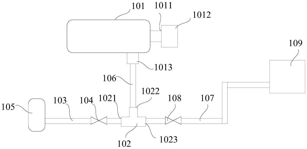
[0048] figure 1 It is a schematic structural diagram of the intake and exhaust device provided in the first embodiment. refer to figure 1 As shown, the air intake and exhaust device for the pressure test operation of the inner tank of the gas heater provided by this embodiment includes a three-way joint 102, an air intake pipe 103, an intermediate pipe 106, an exhaust pipe 107, a muffler tank 109, a first valve 104 and a second valve 108 .

[0049] Specifically, the first interface 1021 of the three-way joint 102 communicates with the gas outlet end of the gas inlet pipe 103, and the gas inlet end of the gas inlet pipe 103 is used to communicate with the gas generating device 105, so that the gas in the gas generating device 105 Transport to the water heater liner 101 for pressure test. A first valve 104 is provided on the intake pipe 103 , and the conduction or closure of the intake pipe 103 is realized by opening or closing the first valve 104 . In practical applications...

Embodiment 2

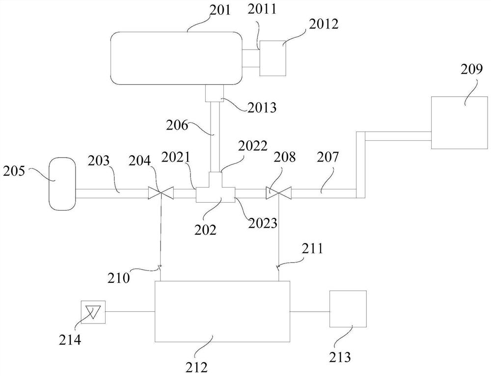
[0078] image 3 It is a schematic structural diagram of the intake and exhaust device provided in the second embodiment. refer to image 3 As shown, the difference between this embodiment and the first embodiment is that the first valve 204 and the second valve 208 are both solenoid valves.

[0079]Specifically, in this embodiment, both the first valve 204 and the second valve 208 are set as electromagnetic valves, which improves the operating efficiency of the first valve 204 and the second valve 208, and further improves the impact of the pressure test process on the intake air. The conduction and closing efficiency of the pipeline 203 and the exhaust pipeline 207 saves the time of air intake, pressure holding and exhaust during the entire pressure test process.

[0080] It should be noted that the solenoid valve used in this embodiment is a common solenoid valve in the prior art, and its specific structure can be referred to the prior art, and will not be repeated here. ...


PUM


Abstract

The invention belongs to the technical field of water heaters, and particularly relates to an air inlet and exhaust device. The air outlet end of an air inlet pipeline and the air inlet end of an exhaust pipeline are connected to a first connector and a third connector of a three-way connector correspondingly, and a first valve and a second valve are arranged on the air inlet pipeline and the exhaust pipeline correspondingly; meanwhile, a middle pipeline is in communication between the second connector of the three-way connector and a pressure testing opening of a water heater inner container so that when the water heater inner container is still located in water, exhaust work can be conducted in the mode that a second valve is opened; and in other words, after pressure maintaining is finished, and when the water heater inner container starts to be lifted, gas in the water heater inner container can be exhausted into air from the middle pipeline and the exhaust pipeline, the pressure testing time is effectively saved, and therefore the pressure testing efficiency of the water heater inner container is improved.

Description

technical field [0001] The invention relates to a water heater, in particular to an air intake and exhaust device used in the pressure test process of the inner tank of the water heater. Background technique [0002] The pressure test of the water heater's inner tank is a necessary work to ensure the quality of the water heater. [0003] Generally, the inner container of the water heater includes a liner opening and an air inlet arranged on the side wall of the liner. Normally, the air intake port and the liner opening are closed. Before the pressure test, the air inlet is communicated with the gas storage tank through the air inlet pipe, and the gallbladder port is closed by the inner gallbladder plug. After the pressure test starts, open the valve on the air intake pipe, let the gas in the gas storage tank flow into the inner tank, after a preset time, close the valve, completely immerse the inner tank in the water tank to keep the pressure, Check for bubbles in the wate...

Claims


Application Information

Patent Timeline
IPC IPC(8): F16L41/02F16L41/16F16L55/033F16K31/02F17C7/00F17C13/00F17C13/04G01M13/00
Inventor 祝兴洋
Owner QINGDAO ECONOMIC & TECHN DEV ZONE HAIER WATER HEATER
Why Eureka
Try Eureka