
Volute and chassis combined assembly structure

A combined assembly and volute technology, which is applied in the field of air conditioning, can solve the problems of easy damage to the sponge, easy to generate noise, buckle breakage, etc., and achieve the effects of reducing the probability of fixing failure, preventing position deviation, and ensuring stability

Inactive Publication Date: 2021-04-16
湖州博驭电器有限公司
View PDF0 Cites 0 Cited by
  • Summary
  • Abstract
  • Description
  • Claims
  • Application Information

AI Technical Summary

Problems solved by technology

The fan assembly in the ducted air conditioner is a component with a high maintenance rate. If you want to repair the fan assembly, you must disassemble the lower volute. Since the upper side of the volute is limited by the top plate of the air conditioner, the volute The lower side of the air conditioner is limited by the chassis of the air conditioner, and the lower volute cannot be disassembled directly. Therefore, if you want to repair the fan assembly, you must first disassemble the chassis of the air conditioner, and then remove the lower volute, which is very laborious and inconvenient.
[0003] Since the lower volute is only connected to the upper volute by a buckle, it is easy to fall off when encountering an impact, and the installation of the lower volute is often carried out by violent crimping on the production line. If the buckle position is not aligned, it is easy to cause buckle broken
At present, the ducted air conditioner is usually pasted with a sponge between the lower volute and the chassis of the air conditioner, and the buckle is prevented from falling off through the extrusion of the sponge, so as to avoid the large vibration deviation of the lower volute in the up and down direction, so that the lower volute The shell installation is more stable and compact, but the sponge is easily damaged, and the damaged sponge is easy to float into the volute and the air conditioner shell. If it is not cleaned and taken out in time, it is easy to generate noise

Method used


Image

  • Volute and chassis combined assembly structure
  • Volute and chassis combined assembly structure
  • Volute and chassis combined assembly structure

Examples


Embodiment Construction

[0030] The following descriptions are only preferred embodiments of the present invention, and are not intended to limit the scope of the present invention. For those skilled in the art, the present invention can have various modifications and changes; all within the spirit and principles of the present invention , any modifications, equivalent replacements, improvements, etc., should be included within the protection scope of the present invention.

[0031] In addition, the terms "vertical", "horizontal", "top", "bottom", "front", "rear", "upper", "lower", "inner" mentioned in the embodiments of the present invention The orientation or positional relationship indicated by , "outside" and so on is based on the attached figure 1 The orientation or positional relationship shown, or the orientation or positional relationship that the product is usually placed in use, is only for the convenience of describing the present invention and simplifying the description, rather than indic...


PUM


Abstract

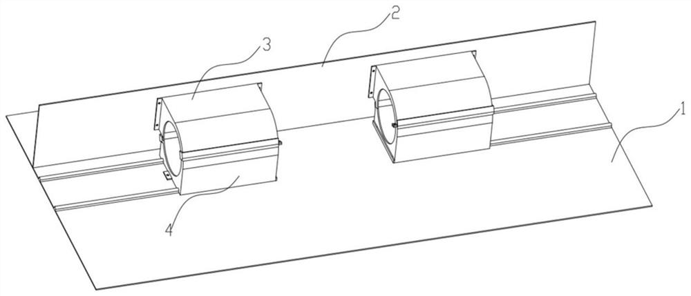
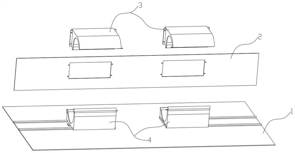
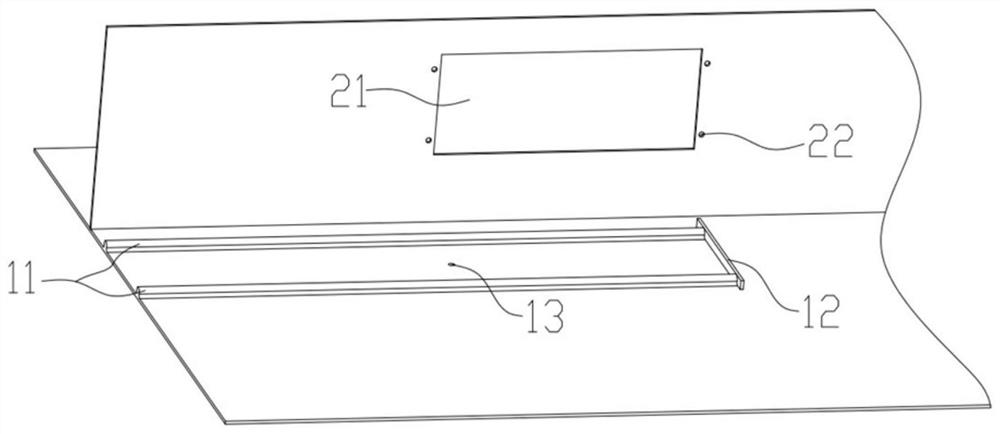
The invention relates to a volute and chassis combined assembly structure which comprises a chassis, a middle partition plate vertically arranged on the chassis, an upper volute arranged in a through hole in the middle partition plate and a lower volute correspondingly connected with the upper volute; and the lower part of the lower volute is detachably connected to the chassis, the upper part of the lower volute is detachably connected to the upper volute, after disassembly, the lower volute and the chassis form a sliding connection structure, a fan assembly can be disassembled after the lower volute slides to the edge of the chassis, an air conditioner shell does not need to be disassembled, disassembly is convenient and fast, and the maintenance efficiency is high. A sliding groove is formed in the lower volute, a sliding rail is arranged on the chassis, sliding between the lower volute and the chassis is smoother through connection and assembly of the sliding groove and the sliding rail, and meanwhile stable and tight installation between the lower volute and the chassis is guaranteed.

Description

Technical field: [0001] The invention relates to the technical field of air conditioners, in particular to a combined assembly structure of a volute and a chassis. Background technique: [0002] The volute is a device used by the ducted air conditioner to accommodate the fan components and regulate the air intake direction. The volute at the present stage includes an upper volute and a lower volute. When assembling, the upper volute is fixed on the partition of the duct machine On the board, the lower volute is connected to the upper volute through buckles. The fan assembly in the ducted air conditioner is a component with a high maintenance rate. If you want to repair the fan assembly, you must disassemble the lower volute. Since the upper side of the volute is limited by the top plate of the air conditioner, the volute The lower side of the fan unit is limited by the air conditioner chassis, and the lower volute cannot be disassembled directly. Therefore, if you want to r...

Claims


Application Information

Patent Timeline
IPC IPC(8): F24F1/0018
Inventor 高俊
Owner 湖州博驭电器有限公司
Learn More