
A floor thermal insulation and sound insulation structure using microcrystalline thermal insulation self-leveling mortar

A technology of self-leveling mortar and floor slabs, which is applied in thermal insulation, floor slabs, and sound insulation, etc. It can solve problems such as lowering the thermal insulation and sound insulation performance of floors, large floor gaps, and mortar fractures, so as to improve thermal insulation and sound insulation performance and reduce the probability of movement. The effect of tight connection

Active Publication Date: 2021-08-27
浙江大森建筑节能科技有限公司
View PDF6 Cites 0 Cited by
  • Summary
  • Abstract
  • Description
  • Claims
  • Application Information

AI Technical Summary

Problems solved by technology

[0002] The floor generally refers to a concrete prefabricated part processed and produced by the prefabrication field. The load-bearing part of the floor layer divides the house into several layers in the vertical direction, and passes the vertical loads such as people and furniture and the self-weight of the floor through the walls, beams or columns. According to the materials used, it can be divided into several forms such as wooden floor slabs, brick arch floor slabs, reinforced concrete floor slabs and steel lining slab load-bearing floors; During the process, the splicing method is usually used for installation. This installation method will prevent the two adjacent floors from being fixed to each other and be easy to move. Eventually, the poured mortar will also break, and at the same time, the adjacent two slabs will The gaps between the slabs are also large, which ultimately reduces the thermal and acoustic performance of the slabs

Method used


Image

  • A floor thermal insulation and sound insulation structure using microcrystalline thermal insulation self-leveling mortar
  • A floor thermal insulation and sound insulation structure using microcrystalline thermal insulation self-leveling mortar
  • A floor thermal insulation and sound insulation structure using microcrystalline thermal insulation self-leveling mortar

Examples


Embodiment Construction

[0018] In order to make the technical means, creative features, goals and effects achieved by the present invention easy to understand, the present invention will be further described below in conjunction with specific embodiments.

[0019] In the description of the present invention, it should be noted that the terms "upper", "lower", "inner", "outer", "front end", "rear end", "both ends", "one end", "another end" The orientation or positional relationship indicated by etc. is based on the orientation or positional relationship shown in the drawings, and is only for the convenience of describing the present invention and simplifying the description, rather than indicating or implying that the referred device or element must have a specific orientation, use a specific Azimuth configuration and operation, therefore, should not be construed as limiting the invention. In addition, the terms "first" and "second" are used for descriptive purposes only, and should not be understood ...


PUM


Abstract

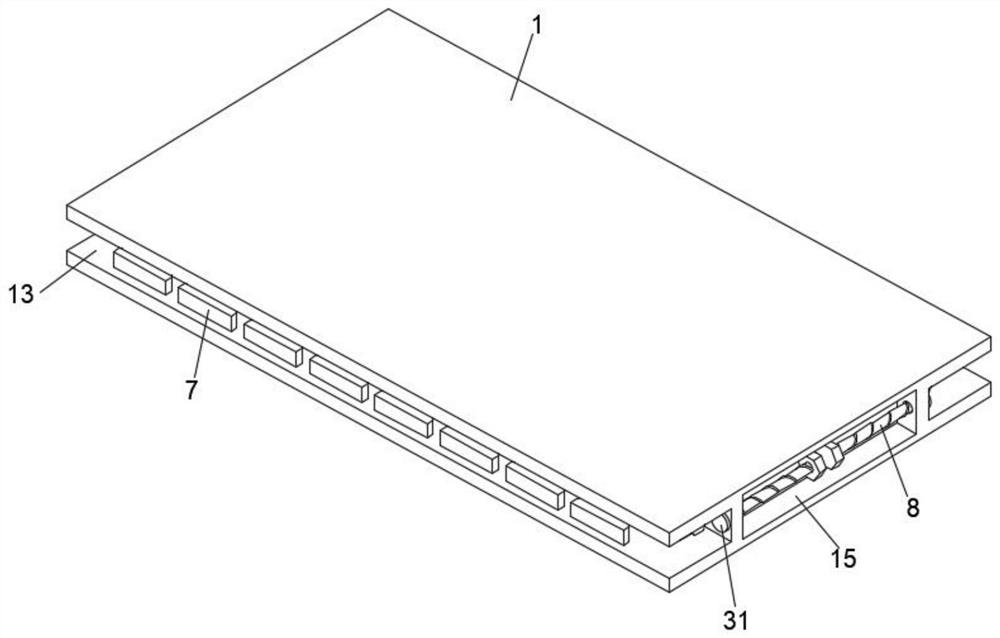
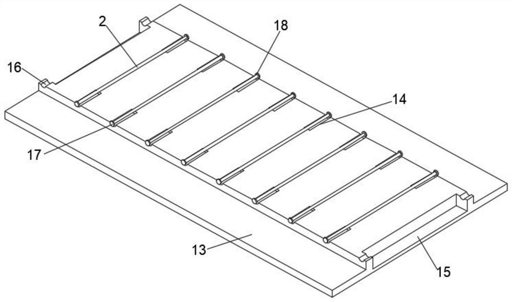
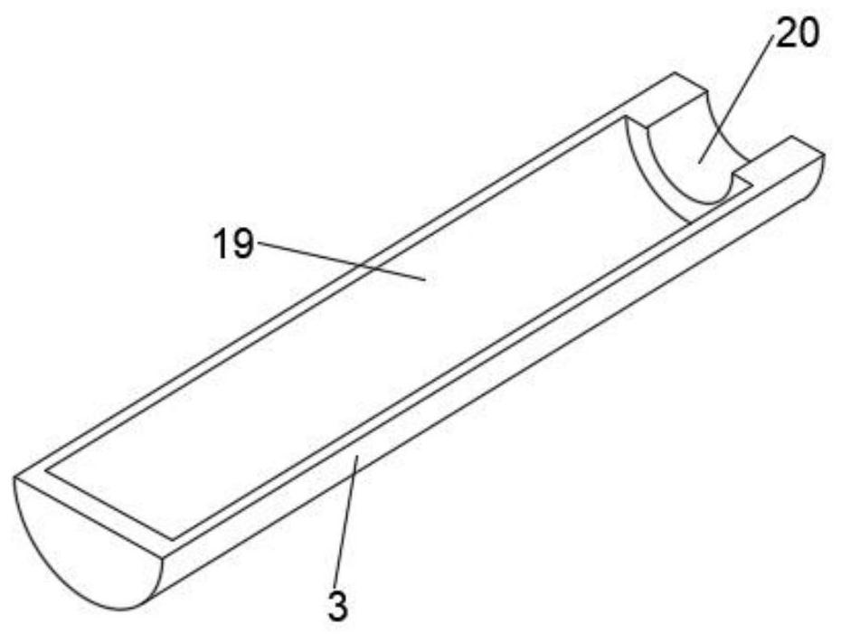
The invention discloses a floor insulation and sound insulation structure using microcrystalline thermal insulation self-leveling mortar. Sixteen connection sleeves are arranged symmetrically on the top, and two connection rods are arranged symmetrically at the outer ends of the connection sleeves inside the floor main body, and an adjusting screw rod is arranged inside the two connection rods. A floor insulation and sound insulation structure using microcrystalline thermal insulation self-leveling mortar according to the present invention belongs to the field of building materials. By setting a detachable trapezoidal block, it can facilitate the fixed connection between two adjacent floors. The probability of its movement is reduced; by setting the adjustable mounting plate, it is convenient to adjust the position of the trapezoidal block, so as to facilitate the interconnection of the floors; by setting the adjusting screw, it is easy to push the adjustable mounting plate to move, and finally improve the insulation of the floor Sound insulation performance.

Description

technical field [0001] The invention relates to the field of building materials, in particular to a floor insulation and sound insulation structure using microcrystalline thermal insulation self-leveling mortar. Background technique [0002] The floor generally refers to a concrete prefabricated part processed and produced by the prefabrication field. The load-bearing part of the floor layer divides the house into several layers in the vertical direction, and passes the vertical loads such as people and furniture and the self-weight of the floor through the walls, beams or columns. According to the materials used, it can be divided into several forms such as wooden floor slabs, brick arch floor slabs, reinforced concrete floor slabs and steel lining slab load-bearing floors; During the process, the splicing method is usually used for installation. This installation method will prevent the two adjacent floors from being fixed to each other and be easy to move. Eventually, the...

Claims


Application Information

Patent Timeline
Patent Type & Authority Patents(China)
IPC IPC(8): E04B5/02E04B1/61E04B1/90
CPCE04B1/6116E04B1/90E04B5/02
Inventor 赵潇武胡玲霞陈清赵享鸿马立涛赵忠强
Owner 浙江大森建筑节能科技有限公司
Learn More