Aerosol particle matter size-based collection device and method
An aerosol particle and collection device technology, which is applied in sampling devices, analysis materials, instruments, etc., can solve the problems of high energy consumption, inability to guarantee work efficiency, and inability to popularize industrial applications in the electrostatic collection method, so as to improve the accuracy of experiments, Ensuring accuracy and saving energy
- Summary
- Abstract
- Description
- Claims
- Application Information
AI Technical Summary
Problems solved by technology
Method used
Image

Examples
Embodiment 1
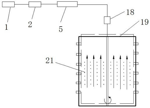
[0040] Such as figure 1 Shown, a kind of aerosol particle matter sub-size collection device, comprises,
[0041] The air intake pipe 1 is arranged horizontally, and the aerosol to be measured is introduced from the air intake pipe 1;
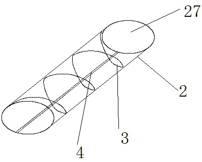
[0042] Such as figure 2 As shown, the dryer 2 is inclined to the plane, the dryer 2 is in a tubular structure, the lower end of the dryer 2 is connected with the air intake pipe 1, and the heating resistance wire 3 for drying the air is arranged inside the dryer 2, and the heating The resistance wire 3 is electrically connected to an external power supply, and the heating resistance wire 3 is arranged spirally around the inner wall of the dryer 2 in the dryer 2. According to the above-mentioned structure, the method of collecting the particles in the dryer 2 is: drying by shaking The device 2 makes the particles attached to the inner wall of the dryer 2 fall into the collection container; further, the inner wall of the dryer 2 is attached wit...
Embodiment 2
[0052] A method for collecting aerosol particles by size, the specific steps are as follows:
[0053] Step 1, the aerosol to be tested (including solid or liquid particles) is introduced into the dryer 2 from the inlet pipe 1;
[0054] Step 2: First, the dryer 2 is preheated for 10 seconds, and then the aerosol to be tested is introduced from the bottom of the dryer 2. The aerosol to be tested is heated by the heating resistance wire 3 to evaporate the water in the liquid particles, and the liquid particles condense after evaporation. Solid particles, the condensed solid particles are attached to the inner wall of the dryer 2, and the dried aerosol is discharged from the top of the dryer 2;
[0055] Step 3, the dried aerosol to be measured is introduced into the ionization device 5, and the ionization area 9 in the ionization device 5 ionizes the particles of the dry aerosol, so that some particles are positively charged, and the dry aerosol enters the particle screening area ...
PUM
 Abstract
Description
Claims
Application Information
PatSnap Eureka turns technology decisions into work you can execute. Powered by our Innovation Knowledge Graph, it runs expert workflows across engineering, life sciences, materials and intellectual property. Get your review-ready output in minutes.


