Water supply method for secondary water supply tank of newly-built building

A technology for secondary water supply and the use of water tanks, applied in water supply devices, water conservation, water supply devices, etc., can solve the problems of inaccurate calculation results, not considering the invalid volume of the water tank, and large invalid volume.

Active Publication Date: 2021-04-16
重庆昕晟环保科技有限公司
View PDF14 Cites 1 Cited by
  • Summary
  • Abstract
  • Description
  • Claims
  • Application Information

AI Technical Summary

Problems solved by technology

[0007] 1) This technology does not distinguish between working days and rest days when statistically analyzing the characteristics of water use. In practice, the water use characteristics of working days and rest days are completely different. For some places, such as schools and office buildings, the Water consumption is much higher than that on rest days, especially during the time period of 6:00-20:00. The average water consumption on working days is several times (3-5 times) the average water consumption on rest days. Statistical analysis is carried out on daily and working days. If the obtained average water consumption is used for water supply control on rest days, it will be obviously too large, which will lead to excessive water storage and completely lose the effect of controlling water supply. Using the resulting average water consumption for water supply control The water supply control on weekdays is relatively small, which may easily lead to insufficient water storage
[0008] 2) The final calculation result of this technology is the inlet flow. It is intended to control the residence time of tap water in the water tank by controlling the inlet flow. However, it is difficult to accurately control the inlet flow in practice, which limits the practical application of this technology.
[0009] 3) This technology does not consider the problem of the invalid volume of the water tank. Since some deposits will gradually remain at the bottom of the water tank, in order to prevent these deposits from flowing out to the user with the outlet pipe of the water tank, the outlet pipe is deliberately closed when installing the outlet pipe of the water tank. Raise it to a certain height from the bottom of the water tank. Usually, the vertical distance between the lower edge of the water outlet pipe and the bottom of the water tank is 10-20cm. Therefore, the water stored below the lower edge of the water outlet pipe of the water tank will not be able to flow out with the water outlet pipe. This part cannot be used. The volume of the water tank used is called the invalid volume. In addition, for the water tank that uses the water pump to control the water outlet of the water tank, if the water outlet pipe is empty, the water pump will be damaged

Method used


Image

  • Water supply method for secondary water supply tank of newly-built building
  • Water supply method for secondary water supply tank of newly-built building
  • Water supply method for secondary water supply tank of newly-built building

Examples


Embodiment 1

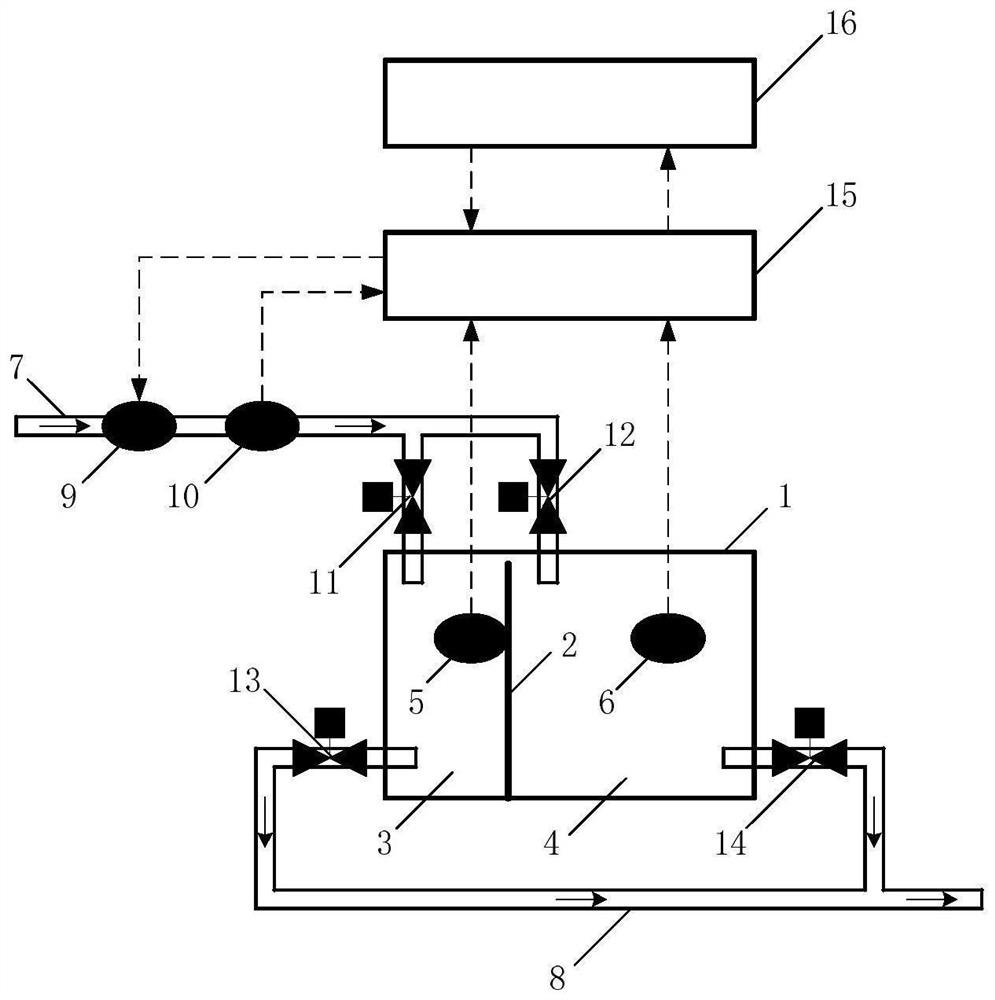
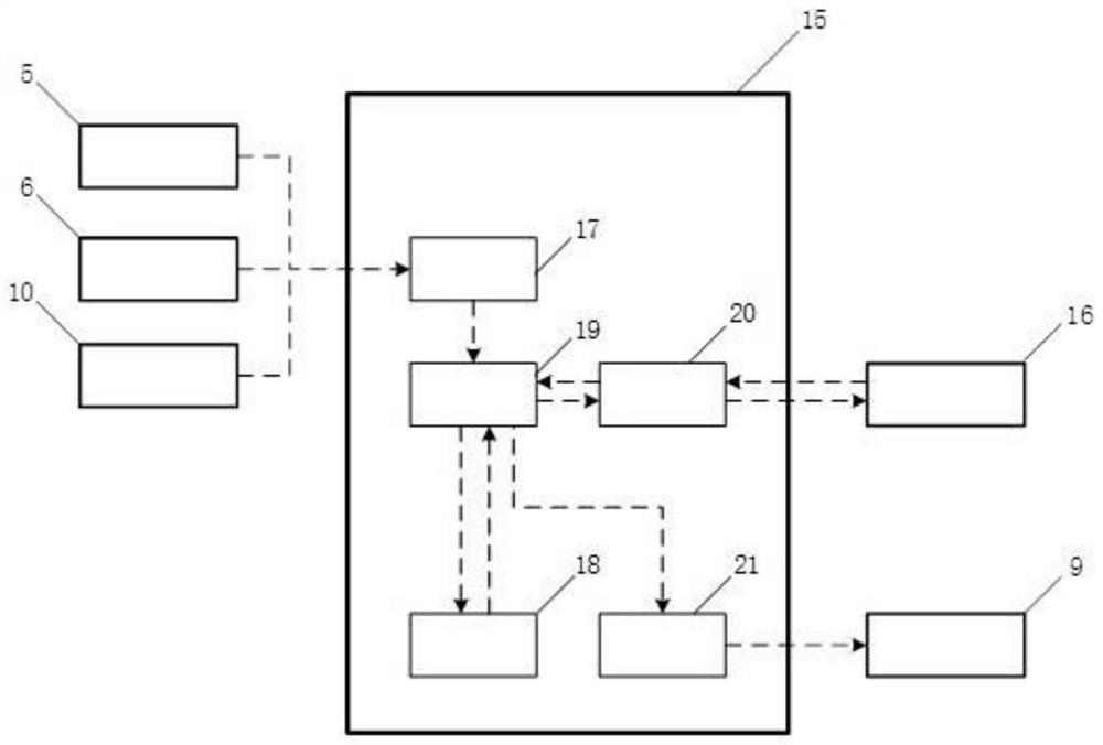
[0101] This embodiment provides a water supply method for the secondary water supply tank of a new building, such as figure 1 As shown, the equipment or device used in the water supply method includes a water tank, a detachable partition, a water inlet solenoid valve, an inlet flowmeter, a first liquid level gauge, a second liquid level gauge, a first water inlet valve, a second water inlet Water valve, first water outlet valve, second water outlet valve, intelligent controller and remote controller. The intelligent controller includes a data acquisition module, a data storage module, a data processing module, a communication module and a control module. The data acquisition module is respectively connected with the inlet flowmeter, the first liquid level gauge, the second liquid level gauge and the data processing module. The modules are respectively connected with the data acquisition module, the data storage module, the communication module and the control module, the commu...

Embodiment 2

[0179] In order to further confirm the accuracy, effectiveness and practicability of the method described in Example 1, the applicant now further describes the scheme of Example 1 in conjunction with specific actual data, as follows:

[0180] Select a new real estate water tank for research. The water tank is a low-level water tank, and the tap water is sent to various users through a frequency conversion pump. Its volume is 50×30×20=30000dm 3 , the longitudinal section area is 1500dm 2 , the minimum liquid level allowed for water storage in the water tank is 2.5dm, and the maximum liquid level allowed for water storage in the water tank is 18dm. It is designed to supply water to 180 households, and only 30 households will live in it at the initial stage of occupancy.

[0181] Under the above-mentioned conditions, the described water supply method for the secondary water supply water tank of the newly-built real estate comprises the following steps:

[0182] In step 1, instal...


PUM


Abstract

The invention discloses a water supply method for a secondary water supply tank of a newly-built building, which comprises the following steps of: 1, dividing the water tank into two water chambers, and selecting one water chamber as a used water tank; 2, calculating the average effluent quantity and the maximum effluent quantity of the used water tank in different time periods of one day of a workday or a rest day; 3, calculating the theoretical remaining water amount of the used water tank at the starting moment of different time periods of one day of a workday or a rest day; 4, calculating the theoretical inflow of the water tank in different time periods of the workday or the rest day at the start time of the different time periods of the workday or the rest day; 5, sending a closing or opening control signal instruction to the water supply control equipment, and circularly finishing the water supply of one day according to the instruction; and 6, calculating the volume ratio of the used water tank, and determining whether the used water tank needs to be changed or not according to the volume ratio. On the premise of meeting the water use requirement, the risk that the microbial index exceeds the standard due to the fact that tap water stays in the water tank for a long time can be effectively reduced.

Description

technical field [0001] The invention relates to the field of secondary water supply of urban water supply pipe network systems, in particular to a water supply method for a secondary water supply water tank of a newly built building. Background technique [0002] Secondary water supply refers to the form of water supply in which urban public water supply is stored, pressurized, and then supplied to users through pipelines. The drinking water (hereinafter referred to as tap water) in the secondary water supply and storage equipment (hereinafter referred to as the water tank) is extracted by a water pump or automatically flows in from the urban water supply pipe network system. The inlet flow of the water tank refers to the flow of tap water at the inlet of the water tank at a certain moment; the outlet flow of the water tank refers to the flow of tap water at the outlet of the water tank at a certain moment; the inflow of the water tank refers to the volume of tap water flowi...

Claims


Application Information

Patent Timeline
IPC IPC(8): G05D9/12E03B1/04E03B11/04
CPCY02A20/00
Inventor 程立高晓昆刘新贵
Owner 重庆昕晟环保科技有限公司
Why Eureka
Try Eureka