Check patentability & draft patents in minutes with Patsnap Eureka AI!

Spring for an injection device

A technology of injection device and coil spring, which is applied in the field of manufacturing coil springs, can solve the problems of expensive installation process and cost of equipment

Pending Publication Date: 2021-04-16
YPSOMED AG
View PDF5 Cites 0 Cited by
  • Summary
  • Abstract
  • Description
  • Claims
  • Application Information

AI Technical Summary

Problems solved by technology

However, devices with such an optical identification function are extremely expensive and complicate the installation process

Method used


Image

  • Spring for an injection device
  • Spring for an injection device
  • Spring for an injection device

Examples


Embodiment Construction

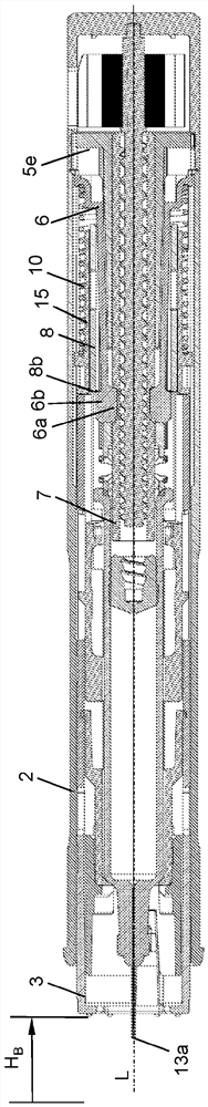
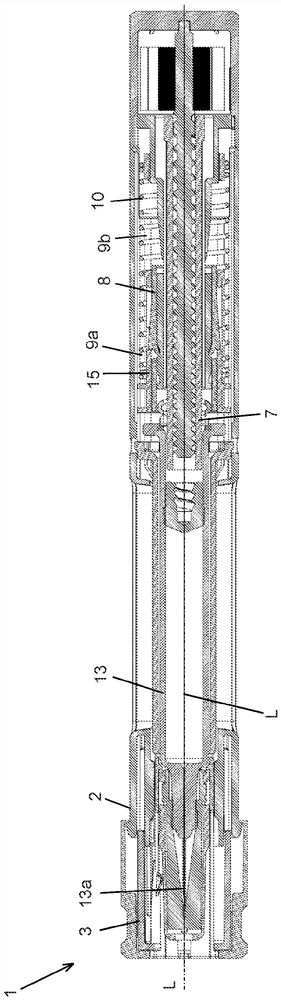
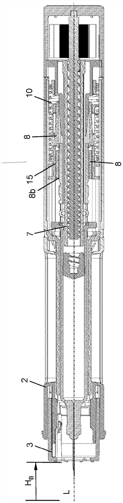
[0040] figure 1 A general perspective view of the helical spring 10 according to the invention is shown. The helical spring 10 is designed as a compression spring and has a winding extending in the axial direction or longitudinal direction of the helical spring 10 with a total of 15 turns. In this case, the helical spring 10 has a length of 114 mm in the unloaded state. It also has an outer diameter of 15 mm. The helical spring 10 is made of a wire having a circular cross section, the wire having a diameter of 0.7 mm. The wires are made of chromel-alloyed spring steel and are also electrically conductive. Such as figure 1 As can be seen in , each of the two outermost turns is connected to each other by point-by-point laser welding.

[0041] The outermost or first turn and the second outermost or second turn of the winding are connected to one another by means of two connection points 20a, 20b, 20c, 20d. The first connection point 20a is approximately 2 mm away from one e...


PUM

PropertyMeasurementUnit
Diameteraaaaaaaaaa

Abstract

The invention relates to an injection device (1) for administering a medical substance, wherein the injection device (1) has a helical spring (10) which has a coil that extends in an axial direction and has at least three windings, wherein two adjacent windings are non-detachably connected to one another at a point in the axial direction by means of a laser-welded connection (20a). The invention also relates to a helical spring (10) of said type and to a method for connecting two windings of the helical spring (10).

Description

technical field [0001] The present invention relates to the field of medical injection devices for administering liquid substances, in particular drugs or medical substances such as insulin preparations and hormonal preparations. The invention relates to an injection device with a helical spring and a method for producing the helical spring. Background technique [0002] Various types of injection devices are known from the prior art for administering liquid medicinal substances. So-called injection devices, known as autoinjectors, allow the automatic tipping of the medicinal substance by means of a pretensioned tilting spring which presses the stopper into the syringe via the piston rod. Such autoinjectors usually have a needle guard which is displaceable in the longitudinal direction by means of a helical spring between a mesial position and a distal position relative to the housing of the autoinjector. After injection, the needle guard is moved by the pretensioned coil ...

Claims


Application Information

Patent Timeline
IPC IPC(8): A61M5/20A61M5/32F16F1/00
CPCA61M5/31F16F1/06A61M5/20A61M5/3243A61M5/3245A61M2207/00F16F1/122A61M5/2033F16F2226/048F16F2228/007F16F2238/026
Inventor P·斯泰特勒B·洛雷茨L·诺塔洛
Owner YPSOMED AG
Features
  • R&D
  • Intellectual Property
  • Life Sciences
  • Materials
  • Tech Scout
  • Unparalleled Data Quality
  • Higher Quality Content
  • 60% Fewer Hallucinations
Learn More