A kind of FA optical fiber end face coating fixture and using method thereof

A technology of optical fiber end face and fixture, which is applied in the direction of injection device, etc., can solve the problems of unsuitable FA optical fiber end face coating, etc., and achieve the effect of improving coating quality, ensuring consistency, and improving coating efficiency

Active Publication Date: 2022-03-11
UNION OPTIC
View PDF8 Cites 0 Cited by
  • Summary
  • Abstract
  • Description
  • Claims
  • Application Information

AI Technical Summary

Problems solved by technology

[0004] However, none of the above-mentioned existing patents is applicable to the coating on the end face of the FA optical fiber with an angle. Therefore, it is necessary to provide a new coating fixture and method to solve the problems existing in the existing coating methods.

Method used


Image

  • A kind of FA optical fiber end face coating fixture and using method thereof
  • A kind of FA optical fiber end face coating fixture and using method thereof
  • A kind of FA optical fiber end face coating fixture and using method thereof

Examples


Embodiment approach

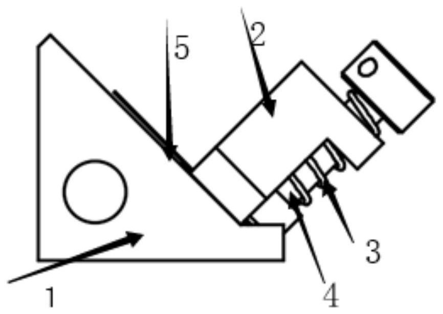
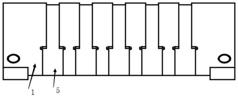
[0036] As an implementation manner, the FA optical fiber end surface coating fixture is connected to a feeding tool, and several V-shaped grooves are arranged in the feeding tool.

[0037] Specifically, a fixed knob is provided on one side of the loading tool, and the FA optical fiber end surface coating fixture is detachably connected to the V-shaped groove by rotating the fixed knob. When loading is required, loosen the fixing knob of the loading tool, put the fixture into the V-shaped groove of the loading tool, and lock the fixing knob to make the positioning surface of the fixture horizontal; after the loading is completed, loosen the fixing of the loading tool Turn the knob, take out the jig, put the FA fiber end-face coating jig and FA fiber into the coating machine to complete the coating.

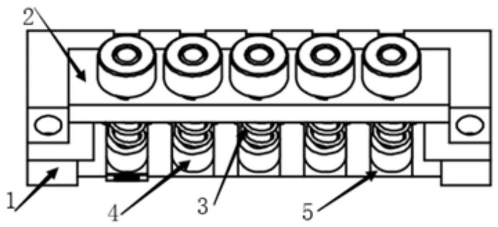
[0038] As an implementation manner, the positioning groove is composed of a first area and a second area, and the width of the first area is larger than that of the second area. T...


PUM


Abstract

The invention discloses a FA optical fiber end surface coating fixture, which comprises a fixture base, a spring bracket, a compression spring and a pull rod. The fixture base is provided with a number of positioning grooves, and the bottom of the spring bracket is fixed on the fixture base. The spring bracket A plurality of through holes are arranged on the top, the pull rod passes through the through holes and the front end of the pull rod matches the positioning groove, and the compression spring is sleeved on the pull rod. The invention also discloses a method for using the FA optical fiber end surface coating fixture. The invention replaces the existing outdated coating method, improves the coating quality and improves the efficiency.

Description

technical field [0001] The invention relates to the field of coating fixtures, in particular to a coating fixture for the end face of an FA optical fiber and a method for using the same. Background technique [0002] FA optical fiber is a commonly used component in the field of optical communication. The front end of the optical fiber is an angled end face, the angle is generally 45 degrees, and the rear end is a thinner glass filament. In order to increase the reflectivity of the end face, the end face with angle needs to be coated. The original coating method is to stick 45°FA on the 45° prism with high-temperature tape for coating. This method is cumbersome to operate and the positioning is not accurate, which often causes problems such as poor product consistency and product drop damage during operation. [0003] In the prior art, there are already fixtures that provide clamping and positioning capabilities for coatings. For example, the Chinese patent with publication ...

Claims


Application Information

Patent Timeline
Patent Type & Authority Patents(China)
IPC IPC(8): B05B13/02
Inventor 刘权肖志全贺鹏
Owner UNION OPTIC
Why Eureka
Try Eureka