
Engine crankshaft cleaning device

A cleaning device and engine technology, applied to the cleaning method using gas flow, cleaning method and utensils, cleaning method using tools, etc., can solve the problems of time-consuming and money-consuming, easy fouling, and damage to the service life of the crankshaft

Pending Publication Date: 2021-04-20
无锡市良名机械制造有限公司
View PDF0 Cites 1 Cited by
  • Summary
  • Abstract
  • Description
  • Claims
  • Application Information

AI Technical Summary

Problems solved by technology

[0003] But it still has some shortcomings when using the crankshaft in practice, as in the existing device, because the crankshaft works for a long time, it is easy to produce impurities and particles to adhere to the surface, and it is easy to foul for a long time and damage the service life of the crankshaft. When cleaning the crankshaft, it needs to be disassembled for cleaning, which wastes unnecessary time and money

Method used


Image

  • Engine crankshaft cleaning device
  • Engine crankshaft cleaning device
  • Engine crankshaft cleaning device

Examples


Embodiment Construction

[0024] The following will clearly and completely describe the technical solutions in the embodiments of the present invention with reference to the accompanying drawings in the embodiments of the present invention. Obviously, the described embodiments are only some, not all, embodiments of the present invention. Based on the embodiments of the present invention, all other embodiments obtained by persons of ordinary skill in the art without making creative efforts belong to the protection scope of the present invention.

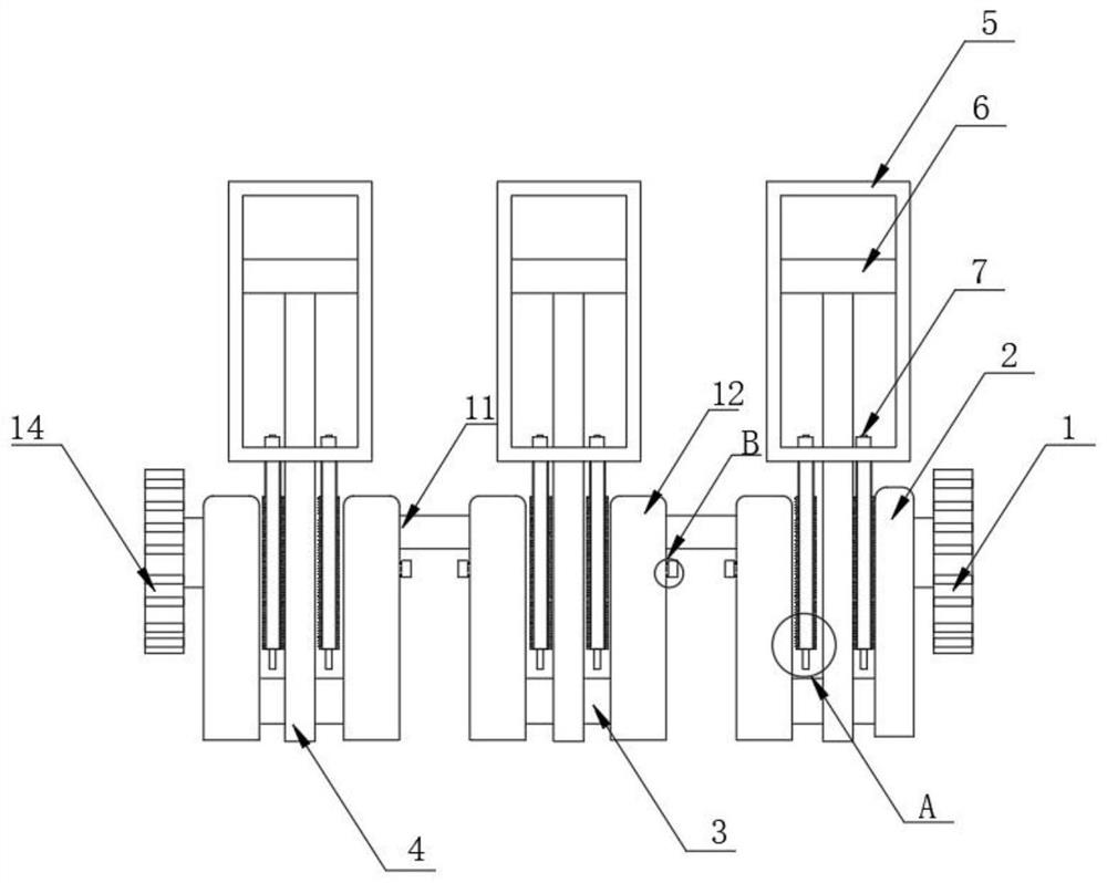
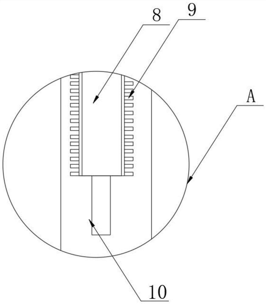
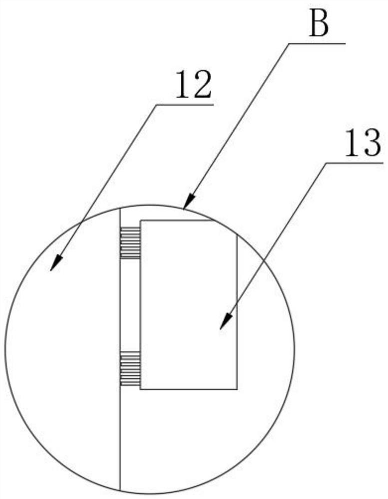
[0025] as attached Figure 1-7 The engine crankshaft cleaning device shown includes a right gear 1, the left side of the right gear 1 is fixedly connected with a left shaft 2, the bottom right side of the left shaft 2 is movably connected with a bottom connecting rod 3, and the bottom connecting rod The middle part of the cylinder 3 is inlaid with a rotating rod 4, and the top of the rotating rod 4 is inlaid with a cylinder 5, and the internal activity of the ...


PUM


Abstract

The invention discloses an engine crankshaft cleaning device, and particularly relates to the field of engines. The engine crankshaft cleaning device comprises a right gear, wherein the left side of the right gear is fixedly connected with a left rotating shaft; the right side of the bottom of the left rotating shaft is movably connected with a bottom connecting rod; a rotating rod is embedded in the middle of the bottom connecting rod; an air cylinder is embedded in the top of the rotating rod; a piston is movably installed in the air cylinder; air inlets are formed in the left side and the right side of the bottom of the air cylinder; brush plates are fixedly installed at the bottoms of the air inlets; and brushes are fixedly installed on the left sides and the right sides of the brush plates. According to the engine crankshaft cleaning device provided by the invention, through combined use of the brush plates and the round brushes, impurities and dirt on the surfaces of the left rotating shaft and the right rotating shaft can be brushed off through the brush plates; and due to the fact that circulation grooves are formed in the brush plates, airflow can be conveyed to the bottom of an air outlet pipe through the circulation grooves, and then the airflow is conveyed out through air outlets in the left side and the right side of the air outlet pipe.

Description

technical field [0001] The invention relates to the technical field of engines, and more specifically, the invention relates to an engine crankshaft cleaning device. Background technique [0002] An engine is a machine that can convert other forms of energy into mechanical energy, including reciprocating piston engines with internal combustion engines, Stirling engines with external combustion engines, steam engines, jet engines, electric motors, etc. The crankshaft is the most important part of the engine. It bears the force transmitted from the connecting rod, converts it into torque and outputs it through the crankshaft and drives other accessories on the engine to work. Subject to bending and torsional loads, including an engine crankshaft cleaning device. [0003] But it still has some shortcomings when using the crankshaft in practice, as in the existing device, because the crankshaft works for a long time, it is easy to produce impurities and particles to adhere to t...

Claims


Application Information

Patent Timeline
IPC IPC(8): B08B1/02B08B1/00B08B5/02
Inventor 陈建立
Owner 无锡市良名机械制造有限公司
Learn More