Low-noise stamping die and method

A stamping die and low-noise technology, applied in the field of stamping noise reduction, can solve the problems of high sound pollution in the working environment, high stamping noise, and serious physical injury to operators

Active Publication Date: 2021-04-20
珠海加特精密工业有限公司
View PDF5 Cites 0 Cited by
  • Summary
  • Abstract
  • Description
  • Claims
  • Application Information

AI Technical Summary

Problems solved by technology

[0004] The purpose of the present invention is to overcome the shortcomings of the above-mentioned prior art, and provide a low-noise stamping die and method, which solves the problems of high stamping noise, great sound pollution to the working environment, and great physical injury to operators in the prior art.

Method used


Image

  • Low-noise stamping die and method
  • Low-noise stamping die and method
  • Low-noise stamping die and method

Examples


Embodiment 1

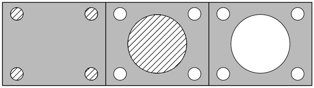
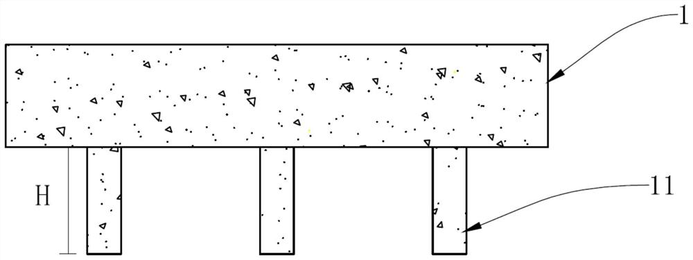
[0028] refer to figure 2 and Figure 4 , the present embodiment provides a low-noise stamping die, including an upper mold base 1 and a lower mold base, and the upper mold base 1 and the lower mold base are sequentially provided with several stations along the conveying direction of the product blank 3, including the first The first station 101, the second station 102, the third station 103, etc., the upper mold base 1 is divided into a plurality of progressive dies in turn, and each progressive die is provided with at least one punch 11 on the parting die. There is a progressive die corresponding to the position, and the lower die base is used to support the product blank 3 and transmit the product blank 3. In one mold clamping, several punches 11 respectively punch the product blank 3 and transfer the product blank 3 Corresponding holes with a certain area are formed on the blank 3, and the projected areas of the punches 11 on the same progressive die parting on the transm...

Embodiment 2

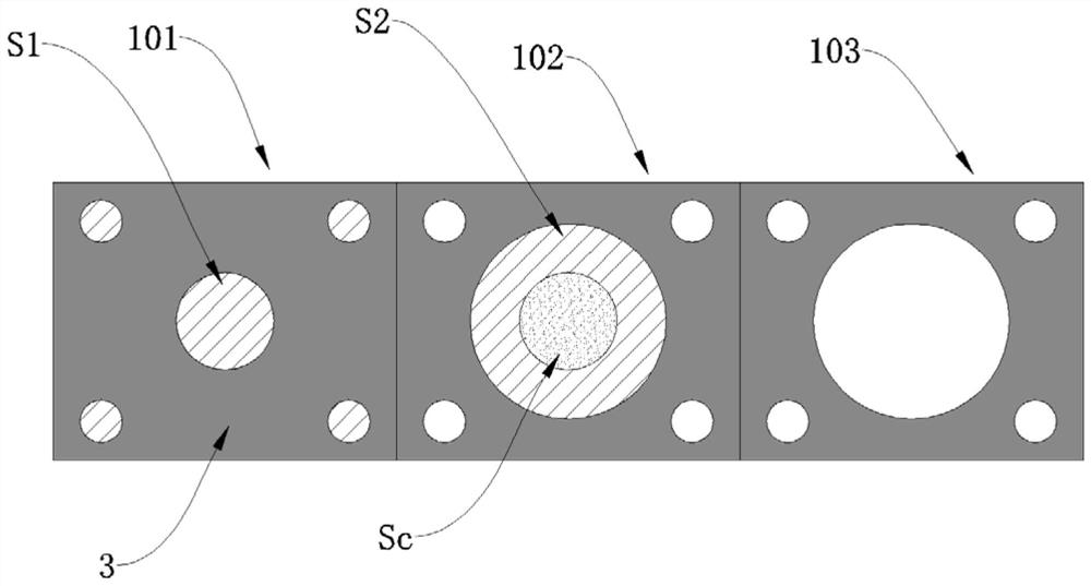
[0038] refer to figure 2 , this embodiment 2 provides a method applied to the above-mentioned low-noise stamping die. The first-stage punch 11 punches out a hole with a projected area of ​​S1 on the product blank 3. On this basis, the second-stage punch 11 The blank 3 of the product is punched out of a hole with a projected area of ​​S2, wherein when the projected area corresponding to the second-stage punch 11 overlaps with the projected area corresponding to the first-stage punch 11, the area of ​​the overlapping area is defined as is Sc, the projected area corresponding to the second-stage punch 11 is S2-Sc; and so on, the projected area S corresponding to each punch 11 is between 90% and 110% Sp, where Sp is the average value of the projected area .

[0039] In addition, if the punch 11 of the previous stage punches out a plurality of relatively scattered holes on the product blank 3, but the punch 11 of the latter stage only overlaps with one or more of the holes, the f...


PUM


Abstract

The invention provides a low-noise stamping die and a method. The low-noise stamping die comprises an upper die base and a lower die base, the upper die base is sequentially provided with a plurality of punches, and the lower die base is used for supporting a product blank and conveying the product blank; in one-time die assembly, the plurality of punches are respectively used for punching the product blank, corresponding hole sites with certain areas are formed on the product blank, and the projection areas of the punches on a transmission plane of the product blank are respectively defined as S1, S2, S3,... Sn, wherein the average value of the projection areas is Sp, and the projection areas S corresponding to all the punches are between 90% of Sp and 110% of Sp. According to the low-noise stamping die, the blanking amount is subdivided and even equally divided, it is guaranteed that the projection area S corresponding to a single progressive die sub-die is within a reasonable range, the blanking hole sites with large-contour appearances are subdivided into multiple times of small-component blanking, the blanking amount corresponding to the projection area each time is controlled, then the total noise value obtained after stamping noise of the multi-stage punches are superposed is reduced, the working noise environment is improved, and harm to the body of an operator is reduced.

Description

technical field [0001] The invention belongs to the technical field of stamping noise reduction, in particular to a low-noise stamping die and method. Background technique [0002] In the field of stamping production, the general classification of noise can be divided into impact noise, punching noise and noise caused by the gap between transmission parts. It is the sound formed by the material breaking due to punching and shearing and the punch suddenly unloading. [0003] In the prior art, the typesetting layout between the multi-stage punches is generally designed according to symmetry, that is, to ensure that the pressure of the punch punches can be evenly distributed when they are in contact with the blank, and to avoid excessive concentration in a certain area, resulting in blanks The force of the material is unbalanced. This situation will lead to a large difference in the punching volume area corresponding to the punch in different progressive dies. In different sta...

Claims


Application Information

Patent Timeline
Patent Type & Authority Applications(China)
IPC IPC(8): B21D37/08B21D35/00G10K11/16
Inventor 李求华何军谭猛
Owner 珠海加特精密工业有限公司
Why Eureka
Try Eureka