Disposer for motor end cover production waste

A technology for producing waste materials and motor end caps, which is applied in grain processing, sounding equipment, instruments, etc., can solve the problems of occupying storage space, affecting the efficiency of processing, affecting the efficiency of collection, etc., and achieve the effect of good use prospects

Inactive Publication Date: 2018-12-14
ANHUI HONGYUAN MACHINERY MFG
View PDF14 Cites 0 Cited by
  • Summary
  • Abstract
  • Description
  • Claims
  • Application Information

AI Technical Summary

Problems solved by technology

[0002] In the process of motor end cover production, a large amount of waste and scrap will be produced. Waste and scrap refer to discarded materials, that is, after considerable use, they have been incomplete or worn out or have exceeded their life span, so that they lose their original functions. , materials that have no value in themselves, recycling these wastes has the meaning of environmental protection. When collecting wastes, there are large gaps between wastes, which occupy a lot of collection space and affect the efficiency of collection. Therefore, it is necessary to Related processing of waste materials; the existing waste processing machines have certain disadvantages in use. They only collect waste materials in a single way and do not squeeze the waste materials, which occupies a lot of storage space and affects the efficiency of processing. It produces a large sound pollution, which has a certain impact in actual use. For this reason, we propose a waste disposal machine for the production of motor end caps

Method used


Image

  • Disposer for motor end cover production waste
  • Disposer for motor end cover production waste
  • Disposer for motor end cover production waste

Examples


Embodiment Construction

[0019] In order to make the technical means, creative features, goals and effects achieved by the present invention easy to understand, the present invention will be further described below in conjunction with specific embodiments.

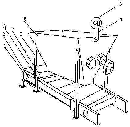
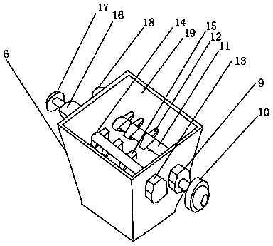
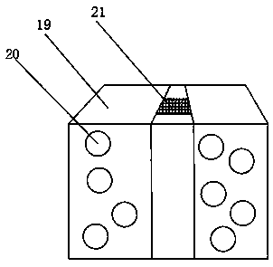
[0020] Such as Figure 1-3 As shown, a waste disposal machine for producing motor end caps includes a support frame 1, the outer surface of the support frame 1 is provided with a speed-regulating motor 2, and the outer surface of the speed-regulating motor 2 is provided with a transmission chain 3, and the outer surface of the transmission chain 3 The surface is provided with a conveyor belt 4, and a vertical rod 5 is arranged at one side of the speed-regulating motor 2 near the outer surface of the support frame 1, and a feeding chamber 6 is fixedly installed on the outer surface of one end of the vertical rod 5, and the feeding chamber The outer surface of the upper end of the chamber 6 is provided with a fixed rod 7, the outer surface of the up...


PUM


Abstract

The invention discloses a disposer for motor end cover production waste. The disposer for the motor end cover production waste comprises a supporting bracket, a speed adjusting motor is arranged on the outer surface of the supporting bracket, and a transmission chain is arranged on the outer surface of the speed adjusting motor. A transmission belt is arranged on the outer surface of the transmission chain, and a vertical rod is arranged at the position which is close to one side of the speed adjusting motor which is located on the outer surface of the supporting bracket. A feeding chamber isfixedly formed in the outer surface of one end of the vertical rod, and a fixing rod is arranged on the outer surface of the upper end of the feeding chamber. An illuminating lamp is arranged on the outer surface of the upper end of the fixing rod, a first speed reducer is arranged on the outer surface of one side of the feeding chamber, a first motor is arranged on the outer surface of one side of the first speed reducer, and a first transmission shaft is arranged on the outer surface of the other side of the first speed reducer. The disposer for the motor end cover production waste is provided with the first transmission shaft, a second transmission shaft and a chamber inner plate, can perform extrusion treatment on sweeps, and reduces occupied space, later collection and recycling are facilitated, good noise-reduction performance is achieved, and a better using prospect is brought.

Description

technical field [0001] The invention relates to the field of waste material treatment, in particular to a waste material treatment machine for motor end cover production. Background technique [0002] In the process of motor end cover production, a large amount of waste and scrap will be produced. Waste and scrap refer to discarded materials, that is, after considerable use, they have been incomplete or worn out or have exceeded their life span, so that they lose their original functions. , materials that have no value in themselves, recycling these wastes has the meaning of environmental protection. When collecting wastes, there are large gaps between wastes, which occupy a lot of collection space and affect the efficiency of collection. Therefore, it is necessary to Related processing of waste materials; the existing waste processing machines have certain disadvantages in use. They only collect waste materials in a single way and do not squeeze the waste materials, which o...

Claims


Application Information

Patent Timeline
Patent Type & Authority Applications(China)
IPC IPC(8): B02C4/08B02C4/42G10K11/162
CPCB02C4/08B02C4/42B02C2201/06G10K11/162
Inventor 徐冬生魏小龙赵红霞魏坤徐磊倪大林杨林郑浩浩常前亮
Owner ANHUI HONGYUAN MACHINERY MFG
Why Eureka
Try Eureka