Rapid marking equipment based on vibration disc discharging

A technology of marking equipment and vibrating disc, applied in welding equipment, laser welding equipment, metal processing equipment, etc., can solve the problems of inability to mark the process, the product cannot be positioned, and it is difficult to fix, and achieves convenient operation, simple structure, cost-saving effect

Pending Publication Date: 2021-04-20
SUZHOU LINGYU ELECTRONICS TECH CO LTD
View PDF0 Cites 0 Cited by
  • Summary
  • Abstract
  • Description
  • Claims
  • Application Information

AI Technical Summary

Problems solved by technology

At present, in order to achieve fast marking, many equipments use vibrating discs to discharge materials. However, most of the current equipment uses vibrating discs to directly discharge materials and then perform marking or other processes. In many cases, products cannot be positioned, which is not good. Fixed, there is jitter, so the marking process cannot be completed well

Method used


Image

  • Rapid marking equipment based on vibration disc discharging
  • Rapid marking equipment based on vibration disc discharging
  • Rapid marking equipment based on vibration disc discharging

Examples


Embodiment Construction

[0030] The present invention will be described in further detail below in conjunction with the accompanying drawings.

[0031] Figure 1-9 Schematically shows a rapid marking device based on vibrating disc discharge according to an embodiment of the present invention.

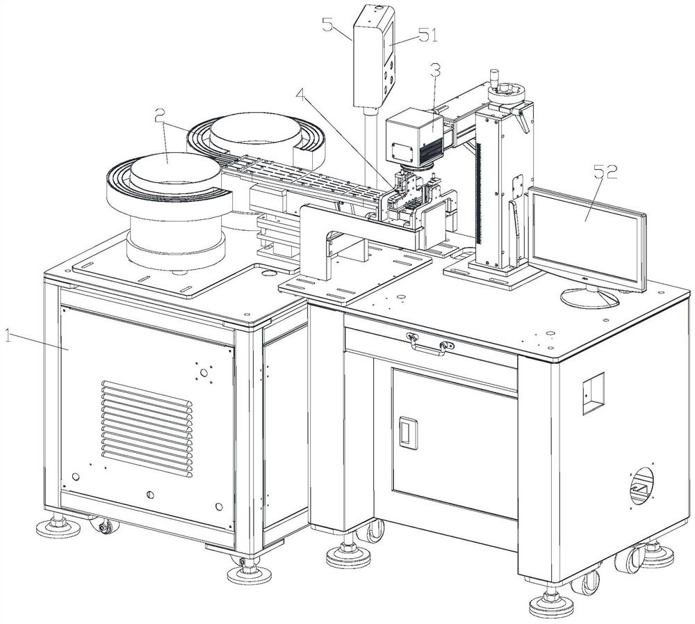
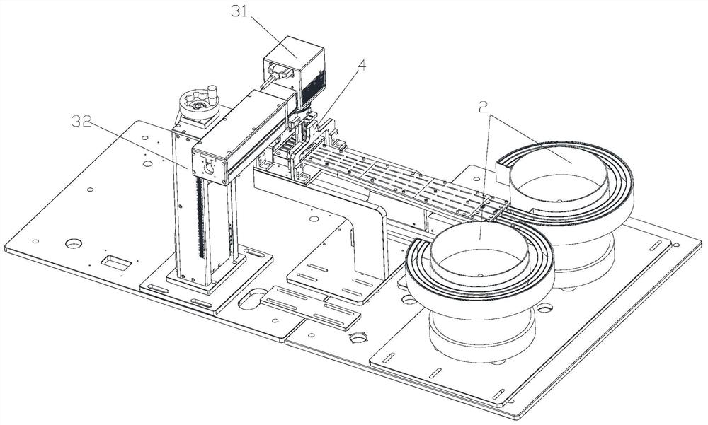
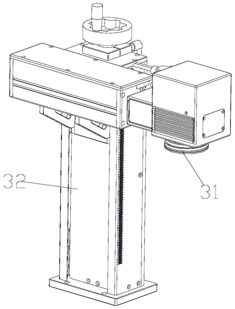
[0032] Such as Figure 1-9 As shown, the rapid marking equipment based on vibrating disc discharge includes a machine 1 and a vibrating disc discharging device 2 and a marking device 3 arranged on the machine 1 . The marking device 3 is arranged at the discharge end of the vibrating disk discharge device 2 . A marking auxiliary device 4 is also included. The auxiliary marking device 4 is arranged on the machine table 1 and is located between the vibrating disc discharging device 2 and the marking device 3 . The vibrating disc discharge device 2 is configured to transport the workpiece 6 to be marked; the marking device 3 is configured to mark the workpiece 6 . The marking auxiliary device 4 is configured t...


PUM


Abstract

The invention discloses rapid marking equipment based on vibration disc discharging. The rapid marking equipment based on vibration disc discharging comprises a machine platform, a vibration disc discharging device and a marking device and further comprises a marking auxiliary device, the vibration disc discharging device and the marking device are arranged on the machine platform, the marking auxiliary device is arranged on the machine platform and is located between the vibration disc discharging device and the marking device, the marking auxiliary device comprises a jig plate, a material pressing mechanism, an air blowing mechanism and a material blocking mechanism, a first conveying channel communicating with the vibration disc discharging device is formed in the jig plate, the material pressing mechanism is matched with a workpiece in the first conveying channel and used for tightly pressing the workpiece, the air blowing mechanism is installed on the material pressing mechanism, matched with the workpiece in the first conveying channel and used for blowing the workpiece after marking is completed, the material blocking mechanism is installed behind the material pressing mechanism, located at the discharging end of the first conveying channel and used for carrying out limitation on the workpiece, and a marking working area of the marking device is located between the material pressing mechanism and the material blocking mechanism. The equipment is simple in structure, convenient to operate, efficient in production, high in speed and saves cost and manpower.

Description

technical field [0001] The invention relates to the field of automation equipment, in particular to a rapid marking equipment based on vibrating disc discharge. Background technique [0002] 3C products have emerged along with the development of the electronics industry in recent years, mainly referring to computer, communication, and consumer electronics products. In this industry, the development of technology is changing with each passing day. , upgrades are frequent, and a large number of new products are launched almost every month, which has become a hot area of ​​product design. [0003] In the 3C electronics industry, many of the products are small-sized products, and the production requires fast speed and high production capacity. Therefore, when making automated machines, the CT is required to be fast. For simple laser marking, it is as fast as possible. At present, in order to achieve fast marking, many equipments use vibrating discs to discharge materials. Howe...

Claims


Application Information

Patent Timeline
Patent Type & Authority Applications(China)
IPC IPC(8): B23K26/02B23K26/14B23K26/362B23K26/70B65G43/08B65G47/14B65G47/74B65G47/88
Inventor 张红伟韦斌
Owner SUZHOU LINGYU ELECTRONICS TECH CO LTD
Why Eureka
Try Eureka