Manipulator operation path planning method and device based on visual positioning

A path planning and visual positioning technology, applied in the direction of manipulators, program-controlled manipulators, manufacturing tools, etc., can solve the problems of deviation of the working path and the decline of the working accuracy, and achieve the effect of improving the working accuracy.

Active Publication Date: 2021-04-20
FOSHAN LONGSHEN ROBOT
View PDF8 Cites 4 Cited by
  • Summary
  • Abstract
  • Description
  • Claims
  • Application Information

AI Technical Summary

Problems solved by technology

[0002]The manipulator is an automatic operation device that can imitate certain movement functions of the human hand and arm, and is used to grab and carry objects or operate tools according to a fixed program; Through programming to complete various expected operations, the structure and performance of both human and robotic machines have their own ad

Method used


Image

  • Manipulator operation path planning method and device based on visual positioning
  • Manipulator operation path planning method and device based on visual positioning

Examples


Embodiment 1

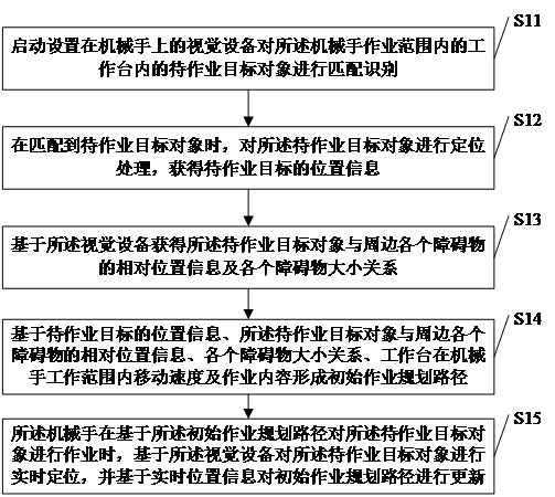
[0043] see figure 1 , figure 1 It is a schematic flow chart of the vision-based positioning-based manipulator operation path planning method in the embodiment of the present invention.

[0044] Such as figure 1 As shown, a method for planning a manipulator operation path based on visual positioning, the method includes:

[0045] S11: Start the vision device set on the manipulator to match and identify the target objects to be operated in the workbench within the working range of the manipulator;

[0046] In the specific implementation process of the present invention, the workbench is the working area controlled by the manipulator on the assembly line; the vision device is a dual-camera device, and the vision device is set on the manipulator to form a joint with the manipulator. hand-eye system.

[0047]Further, the start-up of the vision device installed on the manipulator to match and identify the target object to be operated in the workbench within the working range of ...

Embodiment 2

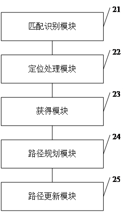
[0066] see figure 2 , figure 2 It is a schematic diagram of the structural composition of the visual positioning-based manipulator operation path planning device in the embodiment of the present invention.

[0067] Such as figure 2 Shown, a kind of robot operation path planning device based on visual positioning, said device includes:

[0068] Matching and identification module 21: used to start the vision device arranged on the manipulator to match and identify the target object to be operated in the workbench within the operation range of the manipulator;

[0069] In the specific implementation process of the present invention, the workbench is the working area controlled by the manipulator on the assembly line; the vision device is a dual-camera device, and the vision device is set on the manipulator to form a joint with the manipulator. hand-eye system.

[0070] Further, the start-up of the vision device installed on the manipulator to match and identify the target ...


PUM


Abstract

The invention discloses a manipulator operation path planning method and device based on visual positioning. The method comprises the steps: starting visual equipment disposed on a manipulator to carry out matching recognition on a to-be-operated target object in a workbench in a manipulator operation range; performing positioning processing on the to-be-operated target object to obtain position information of a to-be-operated target; acquiring relative position information of the to-be-operated target object and each surrounding obstacle and the size relationship of each obstacle based on the visual equipment; forming an initial operation planning path; and when operation is carried out based on the initial operation planning path, real-time positioning is carried out on the to-be-operated target object based on the visual equipment, and the initial operation planning path is updated based on the real-time position information. According to the invention, the operation planning path can be automatically formed according to the position of the to-be-operated target on the workbench and the obstacle condition, the operation planning path is updated in real time in the operation process, and the operation precision is improved.

Description

technical field [0001] The invention relates to the technical field of automatic control, in particular to a method and device for planning a manipulator's working path based on vision positioning. Background technique [0002] The manipulator is an automatic operation device that can imitate certain movement functions of the human hand and arm, and is used to grab and carry objects or operate tools according to a fixed program; The respective advantages of human and robotic machines; in the existing automated production lines, manipulators are basically used for automatic operations, but the paths of existing manipulator operations are basically pre-planned. As the working time goes by, it is easy to cause the deviation of the working path, resulting in the decrease of the working precision. Contents of the invention [0003] The purpose of the present invention is to overcome the deficiencies of the prior art. The present invention provides a method and device for manip...

Claims


Application Information

Patent Timeline
IPC IPC(8): B25J9/16
Inventor 寇慧刘瑞胡国权程瑞瑞
Owner FOSHAN LONGSHEN ROBOT
Why Eureka
Try Eureka