Cutting machine tool changing jig

A technology for cutting machines and jigs, which is applied in the direction of manufacturing tools, fine working devices, stone processing equipment, etc., and can solve the problems of pin breaking, inability to disassemble the knife cover, and knife replacement, etc.

Pending Publication Date: 2021-04-20
JIANGSU UNION SEMICON
View PDF0 Cites 0 Cited by
  • Summary
  • Abstract
  • Description
  • Claims
  • Application Information

AI Technical Summary

Problems solved by technology

[0004] The purpose of the present invention is to provide a cutter changing tool for cutting machine, to solve the above-mentioned background technology when the current personnel use 2 PIN tool changing tool when changing the cutting machine blade, the PIN is more stressed and it is easy to twist the PIN. When changing the blade at the same time, the tool changer with 2 PINs will bear the same reaction force due to the greater force on the PIN and the knife cover will cause the PIN hole on the knife cover to slip, and eventually the knife cover cannot be removed. The problem

Method used


Image

  • Cutting machine tool changing jig
  • Cutting machine tool changing jig
  • Cutting machine tool changing jig

Examples


Embodiment Construction

[0024] The following will clearly and completely describe the technical solutions in the embodiments of the present invention with reference to the accompanying drawings in the embodiments of the present invention. Obviously, the described embodiments are only some, not all, embodiments of the present invention. Based on the embodiments of the present invention, all other embodiments obtained by persons of ordinary skill in the art without making creative efforts belong to the protection scope of the present invention.

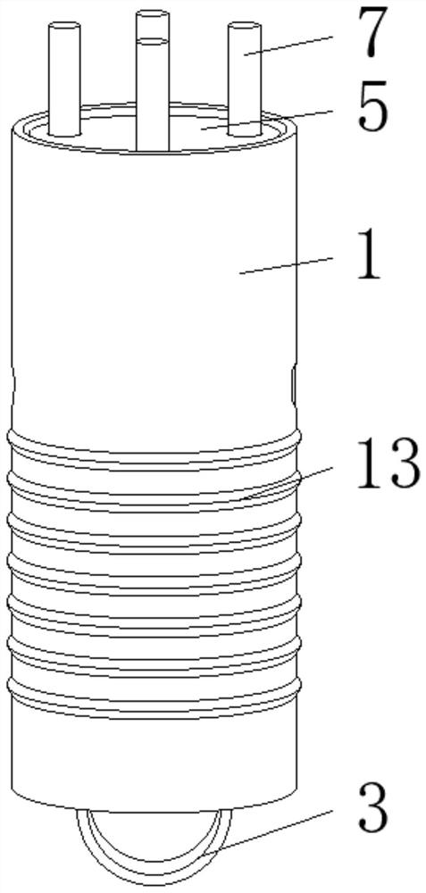
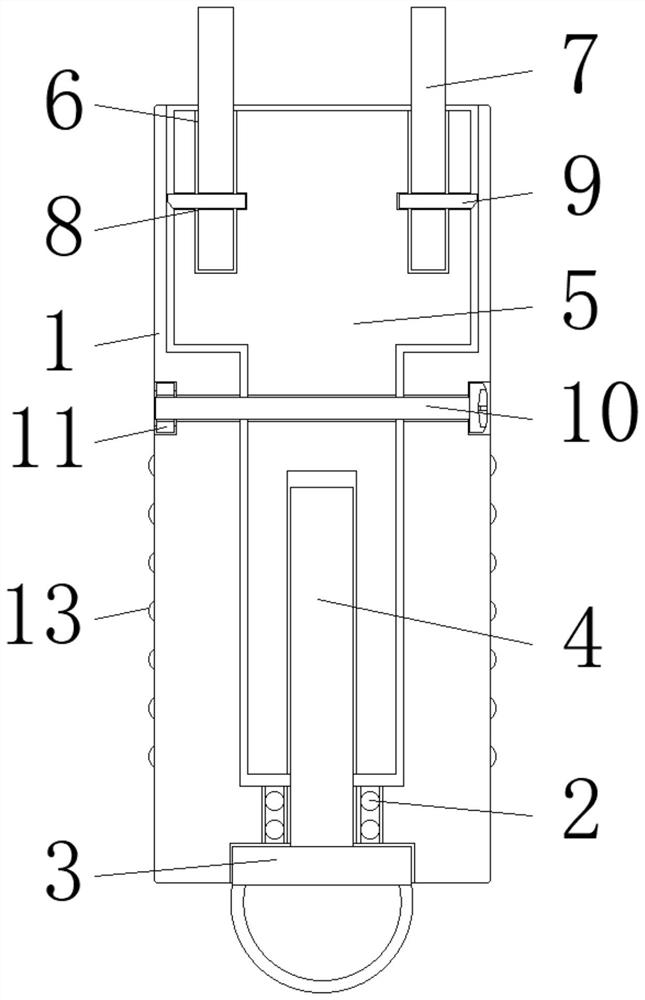
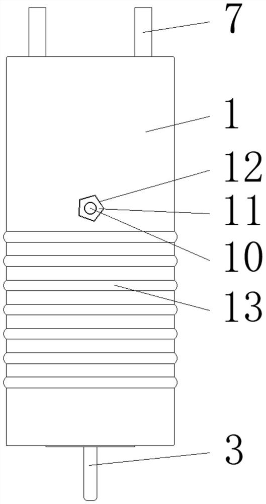
[0025] see Figure 1-4 , the present invention provides a technical solution: a cutting tool changing fixture, including a sleeve 1, a bearing 2, a clamping plate 3, an adjusting rod 4, a fixing rod 5, an installation groove 6, a PIN needle 7, and a limit groove 8 , limit rod 9, screw rod 10, nut 11, card slot 12 and anti-slip pad 13, bearing 2 is installed on the inner bottom of sleeve 1, and the inner side of bearing 2 is connected with adjusting rod 4, and ...


PUM


Abstract

The invention discloses a cutting machine tool changing jig which comprises a sleeve, a fixing rod and a nut. A bearing is mounted at the bottom of the inner side of the sleeve, an adjusting rod is connected to the inner side of the bearing, a clamping plate is fixed to the bottom end of the adjusting rod, the outer side of the top end of the adjusting rod is connected with a fixing rod, and mounting grooves are formed in the top end of the fixing rod. PINs are inserted into the inner sides of the mounting grooves in a penetrating mode, limiting grooves are formed in the inner sides of the bottoms of the PINs, limiting rods are arranged in the limiting grooves, a screw rod is inserted into the middle of the fixing rod in a penetrating mode, the nut is connected to the top end of the screw rod, and a non-slip mat is arranged on the outer side of the bottom of the sleeve. According to the cutting machine tool changing jig, the fixed PINs of the tool changing jig are additionally arranged, the original 2EA is changed into 4EA, the problem that a tool cover with loose teeth cannot be used before is solved, meanwhile, the PINs can be changed, long-term use of the jig is conveniently guaranteed, the fixing rod can be driven to ascend and descend on the inner side of the sleeve through rotation of the adjusting rod, and the PINs are convenient to detach and replace.

Description

technical field [0001] The invention relates to the technical field of a cutting machine tool changing jig, in particular to a cutting machine tool changing jig. Background technique [0002] The cutting machine is a kind of equipment used for cutting silicon wafers in the semiconductor industry. The tool changer is a necessary tool when changing the blade of the cutting machine. It is used to remove and install the blade when the cutting machine is about to reach the end of its life and needs to be changed to change the blade model. role. [0003] At present, when personnel change the cutting machine blade, they use 2 PIN tool changing fixtures, and the PINs are easily twisted due to the large force. The knife cover also bears the same reaction force, which will cause the PIN hole on the knife cover to slip, and eventually the knife cover cannot be removed and the knife can be changed. Therefore, we propose a tool change tool for the cutting machine to solve the above-ment...

Claims


Application Information

Patent Timeline
Patent Type & Authority Applications(China)
IPC IPC(8): B28D5/00
Inventor 孟强许秀真刘明群
Owner JIANGSU UNION SEMICON
Why Eureka
Try Eureka