Integrated oily mud wastewater pipe bundle coagulation and separation reactor
What is Al technical title?
Al technical title is built by PatSnap Al team. It summarizes the technical point description of the patent document.
A technology for reactors and wastewater, applied in liquid separation, separation methods, flocculation/sedimentation water/sewage treatment, etc., to achieve the effects of low energy consumption, convenient installation and use, and less land occupation
Active Publication Date: 2012-07-18
大连贝斯特环境工程设备有限公司
View PDF5 Cites 6 Cited by
Summary
Abstract
Description
Claims
Application Information
AI Technical Summary
This helps you quickly interpret patents by identifying the three key elements:
Problems solved by technology
Method used
Benefits of technology
Problems solved by technology
[0004] (1) The slick oil is collected by the scraper, the sludge is mixed, and the separation is not complete, which affects the quality of the recovered oil;
[0005] (2) Depending on the pressure of the sedimentation tank or the pump to discharge the sludge, the sludge is not discharged in time and thoroughly, which often causes the sludge to expand;
[0006] (3) Relying on the dosing pool or dosing box for dosing, the water distribution is uneven, and mechanical stirring or pipeline mixers are needed to improve the coagulation effect and increase the cost;
[0007] (4) Civil structures are generally used, and the facilities occupy a large area and cannot be moved
[0008]The above shortcomings limit the popularization and use of traditional processing devices
Method used
Image
Click on the blue label to locate the original text in one second.
Reading with bidirectional positioning of images and text.
Examples
Embodiment Construction
[0032] The present invention will be described in detail below with reference to the accompanying drawings.
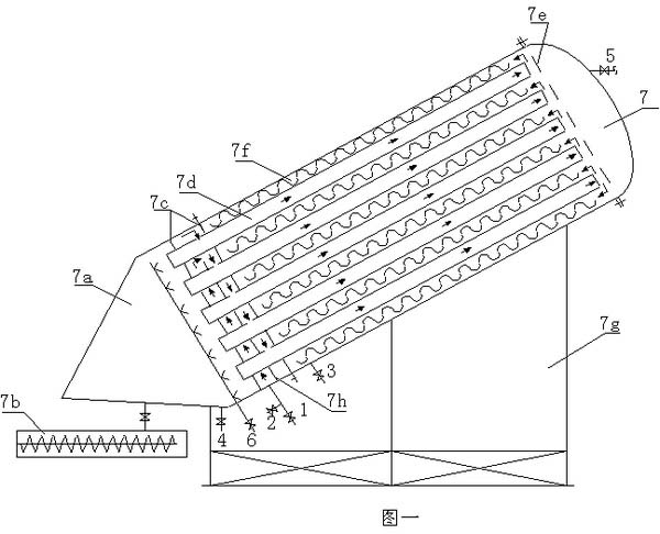
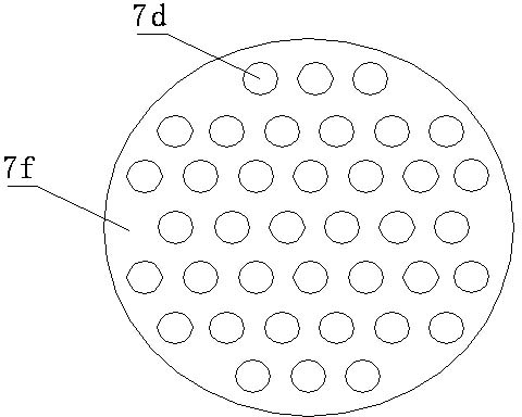
[0033] Integrated coagulation and separation reactor of oily sludge wastewater tube bundle, including reactor main body 7, water inlet pipe 1, dosing pipe 2, water outlet pipe 3, emptying pipe 4, oil collection pipe 5, and compressed air purge pipe 6 arranged on the main body The interior of the reactor mainly includes a mud storage area 7a, a screw conveying mud discharge device 7b, a water retaining plate 7c, a tube bundle sedimentation area 7d, a water distribution plate 7e, a fiber bundle coagulation coarse-graining area 7f, a bracket 7g, and a water baffle 7h, like figure 1 shown.
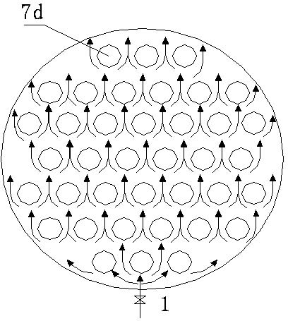
[0034] The specific working principle is as follows. Wastewater containing mud, sand and oil enters the reactor main body 7 through the water inlet pipe 1. The sewage is blocked by the water baffles 7c at the upper and lower ends. Enter the tube bundle sedimentation zone 7d, during ...
PUM
Abstract
The invention relates to an integrated oil-contained wastewater pipe bundle coagulation and separation reactor which comprises a reactor main body, a water inlet pipe, a chemical feed pipe, a water outlet pipe, an emptying pipe, an oil recovering pipe and an air purging pipe are arranged on the main body, and a support is used for supporting the main body. A mud storage region, a water baffle plate, a pipe bundle settling region, a fiber bundle coagulation and coarse graining region, a water distribution plate and the like are mainly installed inside the reactor, the reactor is obliquely installed on the support, the mud storage region is located at the lower part inside the reactor main body, the water baffle plate, a pipe bundle, a water partition plate, the pipe bundle settling region and the fiber bundle coagulation and coarse graining region are located at the middle part, and the water distribution plate and an oil separation plate at the upper part form an oil and water separation region. The reactor has good removal and recovery effect on wastewater containing mud and oil, low energy consumption and small land coverage and is flexible to disassemble, assemble and transport, the mud removal rate can reach more than 95% for oil shale washing wastewater and oil field mining wastewater, the oil recovery rate can reach 90%, the grain size of oil in drained water is smaller than 10 mum, and the mud content is smaller than 10%.
Description
technical field [0001] The invention belongs to the technical field of industrial wastewater treatment, and relates to a tube bundle coagulation separation reactor for oily sludge wastewater. The invention is especially suitable for oily, muddy sand industrial waste cement sand removal, oil recovery and utilization in the fields of petroleum exploitation, chemical industry, steel, electric power and the like. Background technique: [0002] Oily sludge wastewater tube bundle coagulation separation reactor is an integrated reactor for waste cement sand removal and oil recovery and utilization developed on the basis of inclined plate sedimentation and coagulation adsorption technology. [0003] Traditional silt-containing sand and oily wastewater are generally treated separately. Among them, mud and sand removal mainly uses the principle of "shallow sedimentation, and advection, vertical flow or inclined plate sedimentation tanks are used to remove mud and sand. Oil removal ma...
Claims
Application Information
Patent Timeline
Application Date:The date an application was filed.
Publication Date:The date a patent or application was officially published.
First Publication Date:The earliest publication date of a patent with the same application number.
Issue Date:Publication date of the patent grant document.
PCT Entry Date:The Entry date of PCT National Phase.
Estimated Expiry Date:The statutory expiry date of a patent right according to the Patent Law, and it is the longest term of protection that the patent right can achieve without the termination of the patent right due to other reasons(Term extension factor has been taken into account ).
Invalid Date:Actual expiry date is based on effective date or publication date of legal transaction data of invalid patent.