New energy storage battery fixing device

A technology for fixing devices and batteries, which is applied in the direction of electric power devices, battery/fuel cell control devices, secondary batteries, etc. It can solve the problems of fixing batteries of different sizes, inconvenient use of batteries, fixing batteries, etc., so as to avoid loose or Damage, easy to fix, and weaken the effect of shaking force

Inactive Publication Date: 2021-04-20
陈春兰
View PDF10 Cites 1 Cited by
  • Summary
  • Abstract
  • Description
  • Claims
  • Application Information

AI Technical Summary

Problems solved by technology

[0003] Chinese Patent No. CN111267598A provides a new energy vehicle battery fixing device, which belongs to the field of automotive technology, and solves the problem that the existing device cannot adjust the position of the battery, resulting in inconvenient use of the battery; its technical features are: including a base, a lifting seat and a battery installation There is a lifting seat above the base, a battery installation box is fixedly installed on the lifting seat, a battery is installed in the battery installation box, and an adjustment component for adjusting the position of the lifting seat is provided between the base and the lifting seat. There is a protection component on the outside, a limit frame on the outside of the protection component, and a sound-absorbing component inside the limit frame
[0004] However, a new energy vehicle battery fixing device cannot fix batteries of different sizes, and the range of use is small, and because the space inside the fixing seat is small, it is inconvenient to fix the battery inside the fixing seat, which is very inconvenient to use , is not conducive to widespread promotion and popularization

Method used


Image

  • New energy storage battery fixing device
  • New energy storage battery fixing device
  • New energy storage battery fixing device

Examples


Embodiment 1

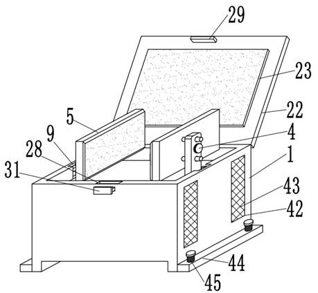
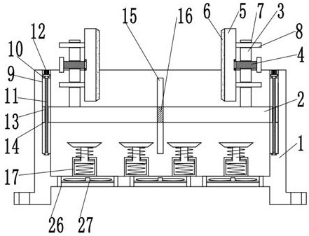
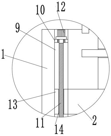
[0042] In summary, a new energy storage battery fixing device provided by the present invention includes a fixing seat 1 and a resisting seat 23. The inside of the fixing seat 1 is slidably connected to the mounting plate 2, and both sides of the outer wall on the top of the mounting plate 2 are welded. There is a clamping seat 3, and the outer wall on one side of the clamping seat 3 is threadedly connected with a fixing bolt 4, and the adjacent ends of the two fixing bolts 4 are movably connected with a clamping plate 5 through a bearing seat, and one side of the clamping plate 5 A rubber pad 6 is arranged on the outer wall of the clamping seat 3, and two guide holes 7 are provided on the outer wall of one side of the clamping seat 3. Two guide rods 8 are welded on the outer wall of the clamping plate 5 away from the other side of the rubber pad 6, and guide Rod 8 is plugged in the inside of guide hole 7, and movable slot 9 is provided on the adjacent side inner wall of fixed ...


PUM


Abstract

The invention relates to the field of new energy and aims at providing a new energy storage battery fixing device. The device comprises a fixing seat and an abutting seat, wherein a mounting plate is slidably connected into the fixing seat, clamping seats are welded to the two sides of the outer wall of the top of the mounting plate, and fixing bolts are in threaded connection with the outer walls of one sides of the clamping seats; clamping plates are movably connected to the adjacent ends of the two fixing bolts through bearing pedestals, rubber pads are arranged on the outer walls of one sides of the clamping plates, and two guide holes are formed in the outer wall of one side of the clamping base. The storage battery fixing device is advantaged in that two clamping plates can clamp and fix storage batteries of different sizes, guide rods can guarantee that the clamping plates cannot rotate when moving, meanwhile, rubber pads can prevent the clamping plates from damaging the storage batteries, and a mounting plate can ascend and descend in a fixing base, and the storage battery can be fixed on the mounting plate and then descends into the fixed seat.

Description

technical field [0001] The invention relates to the field of new energy, in particular to a fixing device for a new energy storage battery. Background technique [0002] With the development of society and the advancement and improvement of science and technology, people's living standards have gradually improved. Most people choose to drive vehicles to go out. With the advancement of technology, new energy vehicles have become people's first choice. The battery of new energy vehicles is the vehicle An important part of the body itself. [0003] Chinese Patent No. CN111267598A provides a new energy vehicle battery fixing device, which belongs to the field of automotive technology, and solves the problem that the existing device cannot adjust the position of the battery, resulting in inconvenient use of the battery; its technical features are: including a base, a lifting seat and a battery installation There is a lifting seat above the base, a battery installation box is fix...

Claims


Application Information

Patent Timeline
Patent Type & Authority Applications(China)
IPC IPC(8): B60K1/04B60L50/64B60L58/26H01M50/249H01M50/244H01M50/242H01M10/613H01M10/625H01M10/6563
CPCY02T10/70Y02E60/10
Inventor 陈春兰
Owner 陈春兰
Why Eureka
Try Eureka