
Moorings for large water level changes

A technology of water level changes and mooring devices, which is applied to ships and other directions, can solve the problems of high cost, high processing and material costs, and inconvenient construction, and achieve the effects of small tension changes, simple structure, and convenient construction

Active Publication Date: 2022-05-31
CHANGJIANG SURVEY PLANNING DESIGN & RES
View PDF6 Cites 0 Cited by
  • Summary
  • Abstract
  • Description
  • Claims
  • Application Information

AI Technical Summary

Problems solved by technology

This method needs to purchase a mooring winch, which is costly. In addition, it needs to monitor the water level change and manually control the winch, so the work process is complicated.
The patent (CN108750009A) discloses a constant tension mooring system for floating structures in sea areas with large tidal ranges. Airbags and screw piles are used to keep the anchor chain tension constant when the water level changes. However, the cost of piling in the sea is too high and special equipment is required Some construction ships are not suitable for piling work due to underwater geological conditions or water depth restrictions.
The patent (CN110920808A) discloses a mooring system suitable for developing water photovoltaics in pumped storage power stations. By building a circle of cages around the photovoltaic array, the bottom of the cages is fixed on the bottom of the water, and the photovoltaic array only needs to be moored with grommets It is used on the net cage to adapt to the change of water level; this kind of scheme needs to set up a large-area net cage, and under harsh environmental conditions, in order to ensure the safety of the net cage structure, the net cage structure needs to be strengthened, and the processing and material costs are high. In addition, the net The box also needs to be restrained in the form of pile foundation, which is inconvenient for construction

Method used


Image

  • Moorings for large water level changes
  • Moorings for large water level changes
  • Moorings for large water level changes

Examples


Embodiment Construction

[0029] The present invention will be further described below in conjunction with the accompanying drawings and specific embodiments.

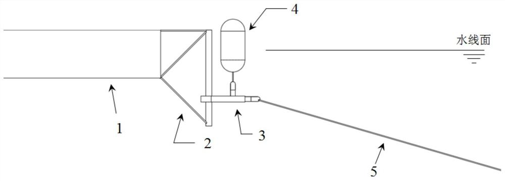
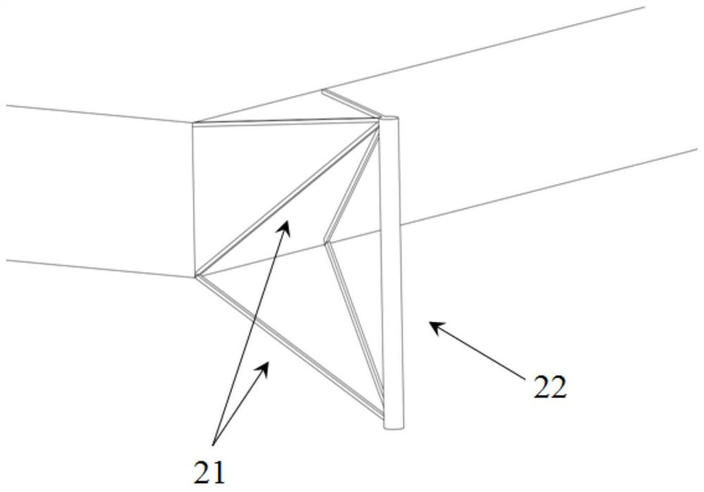
[0032] As shown in Figure 2 and Figure 3, the mooring bracket 2 includes a supporting truss 21 and a vertical sliding rod 22, the supporting truss 21 and the floating

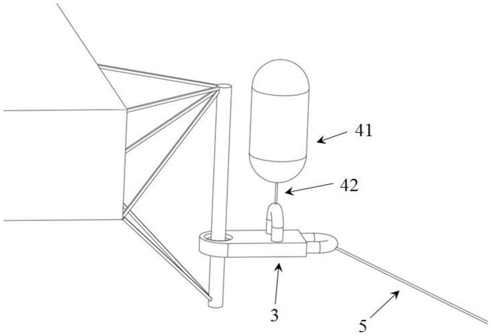
[0035] As shown in FIG. 2, the floating box system 4 includes a floating body unit 41 and a floating body connecting rope 42, and the interior of the floating body unit 41 is hollow,

[0037] The outer wall of the floating body unit 41 is structurally strengthened to avoid collision damage. In conjunction with FIG. 5, the interior of the floating body unit 41 contains many

[0042] The basic principles and main structural features of the present invention have been shown and described above. The present invention is not limited to the above examples


PUM


Abstract

The invention relates to a mooring device suitable for large water level changes. The mooring device includes a floating structure, a mooring bracket, a sliding device, a buoy box system and a mooring cable. The sliding straight rod of the mooring bracket passes through The sliding hole of the sliding device ensures that the sliding device can carry out relative movement in the vertical direction with the mooring bracket; The tension components in the vertical direction are balanced to keep the slide from sinking to the bottom of the mooring structure. When the water level changes, the position of the floating structure moves up and down with the water surface. Since the sliding device and the mooring bracket can slide relative to each other, the floating tank system does not change its position with the lifting of the floating structure under the constraint of the mooring cable. The tension of the mooring lines has always been within a certain range to avoid excessive displacement of floating structures due to water level changes and excessive mooring loads caused by excessive tension of mooring lines.

Description

Mooring for large water level changes technical field The present invention relates to mooring system design and manufacture technical field, be specifically related to a kind of system suitable for large water level change Parking device. Background technique [0002] When the water surface structure floats on the water surface, it is subjected to the force of wind, waves and currents, thereby generating displacement and deflection movement. The mooring system is usually used to restrain the floating structure on the water surface and keep the floating structure on the water surface within a certain range movement and help floating structures withstand harsh environments under extreme conditions. The mooring system is usually composed of anchors, chains or It is composed of a chain engine, etc., and may be equipped with mooring winches, fairleads and other equipment according to the functions of the water structure and the actual operation conditions. ready. In ...

Claims


Application Information

Patent Timeline
Patent Type & Authority Patents(China)
IPC IPC(8): B63B21/00
Inventor 钮新强刘玉亮刘海波喻飞张顺刘爽段斐苏毅邹尤袁博
Owner CHANGJIANG SURVEY PLANNING DESIGN & RES
Learn More