

Automatic cloth unbundling and unfolding device
A cloth, automatic technology, applied in the field of automation, can solve the problems of inability to unpack the rope, low work efficiency, time-consuming and labor-intensive, etc., and achieve the effects of saving labor, improving production efficiency, and saving resources and energy.
- Summary
- Abstract
- Description
- Claims
- Application Information
AI Technical Summary
Problems solved by technology
Method used
Image

Examples
Embodiment Construction
[0021] The technical solutions of the present invention will be further specifically described below through the embodiments and in conjunction with the accompanying drawings.
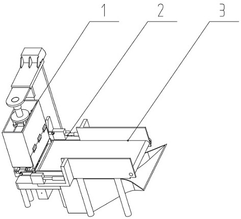
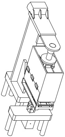
[0022] Examples such as figure 1 , figure 2 , image 3 , Figure 4 , Figure 5 , Figure 6 , Figure 7 As shown, a cloth automatic unbundling and unfolding device includes an unpacking rope device 1, a cloth unpacking device 2, a cloth conveying device 3 and a control device. The packing rope device 1 is fixedly installed at the end of the cloth conveying device 3;
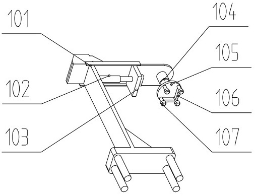
[0023] Unpacking rope device 1, including cutting off fixed frame 101, first cylinder 102, cutting off sliding frame 103, second cylinder 104, first disc 105, cutting knife 106, first rubber claw 107, case shell 108, hinge 109 , door 110, roller 111 and packing rope collecting device;
[0024] The packing rope collection device comprises: the second rubber claw 112, the first claw hand 113, the first motor 114, the rotating shaft ...
PUM
 Abstract
Description
Claims
Application Information