
Thermal forming special-purpose lifting rotary table

A lifting and rotating, thermoforming technology, applied in the direction of lifting frame, lifting device, conveyor, etc., can solve the problems of limited space for rotating table, inability to remove small particles of impurities, low efficiency of steel plate process, etc., to speed up thermoforming efficiency , The overall shape is not damaged, and the effect of preventing the cutting speed from being too fast

Active Publication Date: 2021-04-20
ANHUI UNIV OF SCI & TECH
View PDF6 Cites 0 Cited by
  • Summary
  • Abstract
  • Description
  • Claims
  • Application Information

AI Technical Summary

Problems solved by technology

[0003] However, there are the following problems in the use of a special lifting and rotating table for thermoforming in the market at present. After a certain amount of steel plates fall into the rotary table, the steel plates located at the bottom of the rotary table are difficult to be manually removed, so that the rotary table cannot continuously supply steel plates to the conveying equipment, resulting in low efficiency of the thermoforming process of the entire steel plate; b. Traditional thermoforming The special lifting and rotating table is limited to provide a platform for the cut plate, and it cannot remove the small particles attached to the end surface of the steel plate during the actual transportation process, which will easily lead to deformation of the steel plate in the subsequent stamping process

Method used


Image

  • Thermal forming special-purpose lifting rotary table
  • Thermal forming special-purpose lifting rotary table
  • Thermal forming special-purpose lifting rotary table

Examples


Embodiment Construction

[0026] The embodiments of the present invention will be described in detail below with reference to the accompanying drawings, but the present invention can be implemented in many different ways defined and covered by the claims.

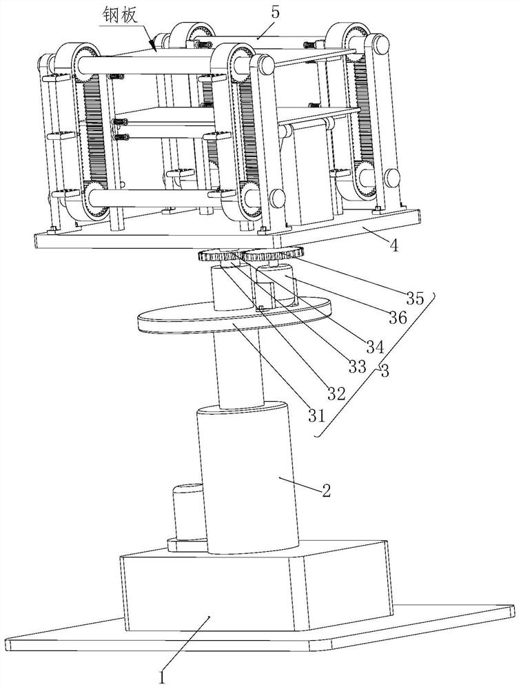
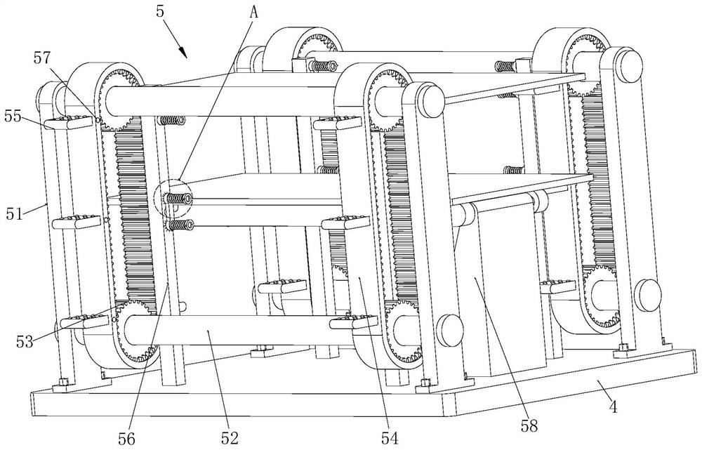
[0027] Such as Figure 1 to Figure 6 As shown, a lifting and rotating table dedicated to thermoforming includes a fixed base 1, a hydraulic telescopic rod 2, a rotating mechanism 3, a rectangular plate 4, and a placement mechanism 5. The center position of the top of the fixed base 1 is fixed with a hydraulic telescopic Rod 2, the top of the hydraulic telescopic rod 2 is connected with a rotating mechanism 3, the top of the rotating mechanism 3 is connected with a rectangular plate 4, and the top of the rectangular plate 4 is provided with a placement mechanism 5;

[0028] The rotating mechanism 3 includes a convex disk 31, a rotating groove 32, a rotating support shaft 33, a first gear 34, a second gear 35 and a drive motor 36, and the convex disk ...


PUM


Abstract

The invention relates to a thermal forming special-purpose lifting rotary table. The thermal forming special-purpose lifting rotary table comprises a fixed base, a hydraulic telescopic rod, a rotary mechanism, a rectangular plate and a placing mechanism, wherein the hydraulic telescopic rod is fixedly installed at the center position of the top of the fixed base through bolts, the rotary mechanism is connected to the top of the hydraulic telescopic rod, the rectangular plate is connected to the top of the rotary mechanism, the placing mechanism is arranged at the top of the rectangular plate, a convex disc is fixedly installed at the top of the hydraulic telescopic rod through bolts, a rotating groove is formed in the center position of the top of the convex disc, a rotating supporting shaft is connected in the rotating groove in an inserted manner, and roll balls are arranged between the bottom of the rotating supporting shaft and the bottom of the rotating groove, the upper end face of the rotating supporting shaft is welded to the lower end face of the rectangular plate by spot welding, and the outer wall of the rotating supporting shaft is provided with a first gear in a welded manner. By means of the thermal forming special-purpose lifting rotary table, steel plates can be stacked continuously, and automatic blanking of the steel plates is realized, meanwhile, the surfaces of the steel plates can be cleaned in the blanking process, and the appearances of the steel plates will not be damaged.

Description

technical field [0001] The invention relates to the technical field of thermoforming steel processing equipment, in particular to a special elevating and rotating table for thermoforming. Background technique [0002] Thermoformed steel plate technology refers to a technology that heats the steel plate at a high temperature of 950°C and then forms it once, and then cools it rapidly to comprehensively improve the strength of the steel plate. The thermoformed steel plate has ultra-high strength and extremely high mechanical safety. The main process is: the whole steel plate falls into the placement equipment after being shaped by the cutting equipment, and is stacked on the placement equipment one by one, and then the steel plates stacked on the placement equipment are placed on the conveying equipment, and the plates are transported to In the heating chamber, the heated steel plate is clamped by the mechanical arm into the stamping equipment to complete the stamping. The lif...

Claims


Application Information

Patent Timeline
Patent Type & Authority Applications(China)
IPC IPC(8): B65G23/04B65G47/34B65G47/52B66F7/18B66F7/28
Inventor 郭永存严建文王爽苏国用王文善赵艳秋
Owner ANHUI UNIV OF SCI & TECH
Learn More