Photovoltaic anti-glare panel

An anti-glare panel and photovoltaic technology, applied in photovoltaic power generation, protective equipment, electric vehicles, etc., can solve problems affecting the power generation efficiency of anti-glare panels, and achieve the effect of improving power generation efficiency and reducing shading

Active Publication Date: 2021-04-20
广州北环智能交通科技有限公司 +2
View PDF20 Cites 2 Cited by
  • Summary
  • Abstract
  • Description
  • Claims
  • Application Information

AI Technical Summary

Problems solved by technology

[0004] For the related technologies mentioned above, the inventor thinks that the size of the distance between the anti-glare boards and the size of each anti-glare board itself have corresponding standards (if the distance is too small or the anti-glare board is too small, it will not work well. to the anti-glare effect), so when the light shines on the first anti-glare plate, part of its shadow may be projected on the second anti-glare plate, which will affect the power generation efficiency of the anti-glare plate

Method used


Image

  • Photovoltaic anti-glare panel
  • Photovoltaic anti-glare panel
  • Photovoltaic anti-glare panel

Examples


Embodiment 1

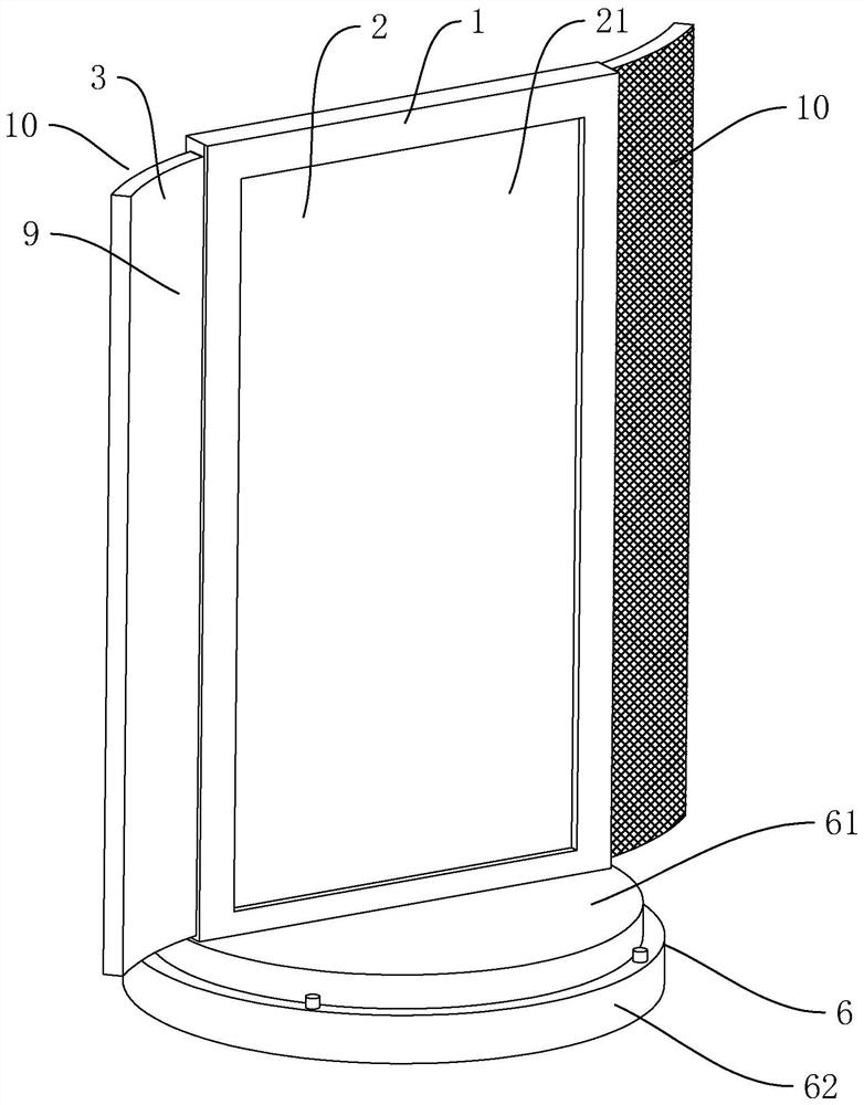
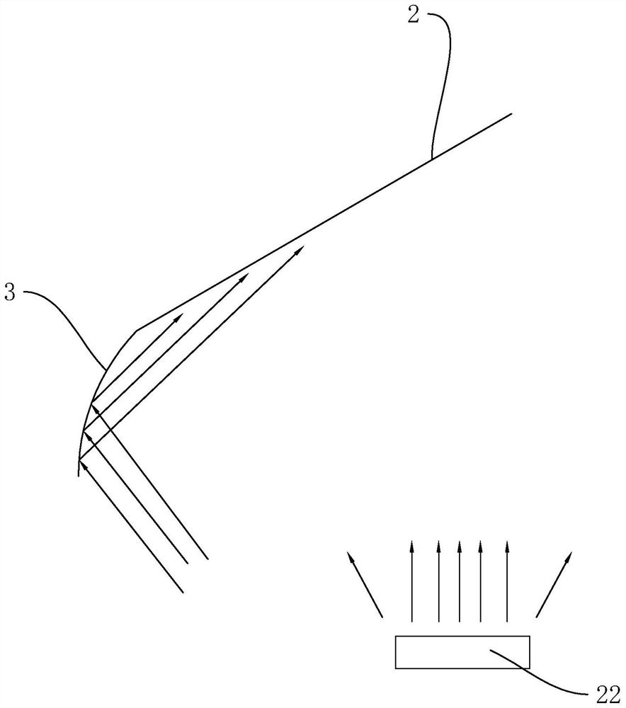
[0037]EXAMPLE 1, the present application discloses a photovoltaic anti-glare plate. Referfigure 1 withfigure 2 The photovoltaic glare plate includes a base 6, a frame 1 fixed to the base 6 and a photovoltaic assembly 2 provided in the frame 1, the photovoltaic assembly 2 is a double-sided photovoltaic assembly 2, so that the light-free glare plate can be collected on both sides. The light source is powered, and the electrochromic plate 3 is also attached to the left and right of the frame 1, the electrochromic plate 3 is electrochromic glass, and is curved, and the bending direction of the two electrochromic plates 3 is exactly the opposite. The electrochromic plate 3 is a smooth surface 9 in the inner recess, at night, the light of the car is directly illuminated on the photovoltaic assembly 2, and the car lamp 22 light in the smooth surface 9 can be used. Reflected onto the photovoltaic assembly 2 for power generation, so that the anti-glare plate can collect more weak light at ni...

Embodiment 2

[0042]Example 2, seeFigure 7 withFigure 8 The present embodiment differs from the first embodiment in that the automatic reset mechanism 7 includes a cylindrical body 77, a sealing plate one 78, and a sealing plate 2 79, and the upper end of the cylinder 77 is fixedly sealed with the turntable 61, and the lower end and fixation of the cylinder 77 The disk 62 rotates the sealing connection, the sealing plate one 78 and the seal two are provided in the cylinder 77, the sealing plate one 78 is fixed to the turntable 61, the sealing plate 2 79 is fixedly connected to the fixed disk 62, the sealing plate one 78 and the sealing plate 2 79 is connected to the rubber strip 14, the sealing plate one 78, the sealing plate 2 79, the cylinder 77, the turntable 61, and the fixing disk 62 constitute two constant closed air pressure chambers 80, and the two air pressure chamber 80 is filled. There is a gas, the air pressure in the two air pressure chambers 80 is the same, and the atmospheric press...


PUM


Abstract

The invention relates to a photovoltaic anti-glare panel which comprises a frame and a photovoltaic module arranged in the frame, an electrochromic plate is installed on the outer side wall of the frame, a light intensity sensor and a power supply controller connected to the output end of the light intensity sensor are further arranged on the frame, and the power supply controller is connected to the electrochromic plate and pre-provided with a color changing threshold value. When a detection signal output to the power supply controller by the light intensity sensor is greater than or equal to a threshold value, the power supply controller controls the electrochromic plate to be in a light transmission state; and when the detection signal output to the power supply controller by the light intensity sensor is smaller than the threshold value, the power supply controller controls the electrochromic plate to be converted into a shading state. The photovoltaic anti-glare panel not only can output large electric energy in the daytime, but also can collect car lamp light for power generation at night.

Description

Technical field[0001]The present invention relates to the field of highway facilities, in particular, to a photovoltaic glare plate.Background technique[0002]With the continuous improvement of our national road network, effective measures have been taken and prevent accidents of accidents, and is the key points and difficulties of road safety management. In order to ensure the safety of the road, the anti-glare facility is provided on the road, and the anti-glare facility refers to a constructor disposed in a central separation belt, which is a device that guarantees the nighttime of the night driving without being disturbed to the front light. The best way to solve the problem of glare on highways is to set anti-glare facilities, using comparative general: anti-glare board, anti-glare network, tree planting.[0003]At present, there is also a photovoltaic anti-glare board in the market, and the photovoltaic assembly is installed in the anti-glare, which can carry a photovoltaic power...

Claims


Application Information

Patent Timeline
Patent Type & Authority Applications(China)
IPC IPC(8): E01F7/06H02J7/35
CPCY02E10/56
Inventor 赖伟勇麦耀华方健海周界龙张群芳高彦艳
Owner 广州北环智能交通科技有限公司
Why Eureka
Try Eureka