Reservoir sediment pumping system based on robot algorithm shaping artificial eddy
An extraction system and robot technology, applied to mechanically driven excavators/dredgers, etc., can solve problems such as difficult adjustment, high energy consumption, and low efficiency of sediment suction, and achieve improved sand mining efficiency, easy control, and energy saving The effect of sand mining costs
- Summary
- Abstract
- Description
- Claims
- Application Information
AI Technical Summary
Problems solved by technology
Method used
Image
Examples
Embodiment 1
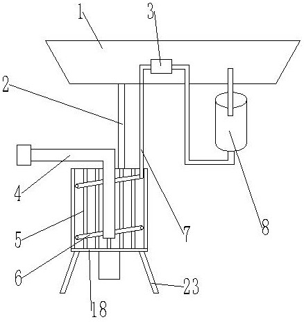
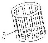
[0053] Such as Figure 1-5 As shown, a reservoir sediment pumping system based on robot algorithm to shape artificial vortex, comprises hull 1, and described hull 1 is provided with vortex former 18; Said vortex former 18 comprises water cage 5 and nozzle 6, and described Spout pipe 6 is arranged on the inner side of water cage 5, and described spray pipe 6 is connected with first water pump 8 by connecting pipe 7, and described connecting pipe 7 is flexible pipe, and described spray pipe 6 inside is provided with a plurality of shower nozzles 9; The inside of the water cage 5 is provided with a sediment pipe 4; the sediment pipe 4 is connected to the water inlet of the sediment pump, and the water outlet of the sediment pump is connected to an outlet pipe; the connecting pipe 7 is provided with a flow regulator 3 .
[0054]The upper and lower ends of the water cage 5 are provided with circular rings, and a plurality of connecting pipes are arranged between the circular rings...
Embodiment 2
[0060] Such as Figure 1-5 As shown, a reservoir sediment pumping system based on robot algorithm to shape artificial vortex, comprises hull 1, and described hull 1 is provided with vortex former 18; Said vortex former 18 comprises water cage 5 and nozzle 6, and described Spout pipe 6 is arranged on the inner side of water cage 5, and described nozzle pipe 6 is connected with the first water pump 8 through connecting pipe 7, and the inside of described nozzle pipe 6 is provided with a plurality of nozzles 9; The inside of described water cage 5 is provided with sediment pipe 4. The sand pipe 4 is connected to the water inlet of the sand pump, and the water outlet of the sand pump is connected to an outlet pipe; the connecting pipe 7 is provided with a flow regulator 3 . The hull 1 is provided with a hoist, and the wire rope of the hoist is connected with the connecting belt 2 . The position of the swirl former 18 at the bottom of the water is adjusted by setting the winch.
Embodiment 3
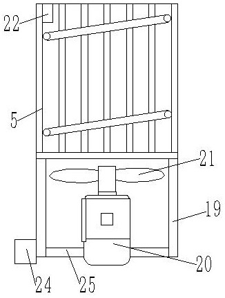
[0062] combine Figure 9 As shown, the difference from Embodiments 1 and 2 is that a motor support 19 is provided on the lower side of the water cage 5, a motor 20 is provided on the upper side of the motor support 19, and a fan blade 21 is connected to the output shaft of the motor 20. , the fan blade 21 is located inside the water cage 5, the motor 20 is a variable frequency motor, the motor 20 is provided with a waterproof device, the motor 20 drives the fan blade 21 to rotate, and cooperates with the first water pump 8 to adjust The size of the vortex, the vortex can fully stir the sediment at the bottom of the water, so that the sediment can be fully mixed with the water.
[0063] The upper side of the water cage 5 is provided with a sensor 22, and the sensor 22 is a force-sensitive sensor; the outside of the sensor 22 is provided with a waterproof device, and the sensor 22 is connected with the water cage 5 by a waterproof device, and the number of the sensors 22 is Mor...
PUM
 Abstract
Description
Claims
Application Information
 - R&D
- Intellectual Property
- Life Sciences
- Materials
- Tech Scout
- Unparalleled Data Quality
- Higher Quality Content
- 60% Fewer Hallucinations
Browse by: Latest US Patents, China's latest patents, Technical Efficacy Thesaurus, Application Domain, Technology Topic, Popular Technical Reports.
© 2025 PatSnap. All rights reserved.Legal|Privacy policy|Modern Slavery Act Transparency Statement|Sitemap|About US| Contact US: help@patsnap.com


