
Manufacturing method of landscape intercepting well body

A production method and technology of intercepting wells, which are applied in the fields of manufacturing tools, strengthening molding, climate change adaptation, etc., can solve the problems of heavy installation workload, high cost, and high requirements for printing equipment

Active Publication Date: 2021-04-20
常州市君杰水务科技有限公司
View PDF10 Cites 0 Cited by
  • Summary
  • Abstract
  • Description
  • Claims
  • Application Information

AI Technical Summary

Problems solved by technology

However, this kind of interception well body is formed by integral printing, which is difficult to implement. It not only has very high requirements for printing support materials, but also has high requirements for printing equipment, and is also easily restricted by transportation.
Secondly, during the production, it is necessary to manually pass the horizontal steel bars and vertical steel bars into the corresponding reserved reinforcement holes of the vertical beams and horizontal rib beams. The workload of installation is relatively large, and the efficiency cannot be further improved.
As people's requirements for urbanization and beautification are increasing, the beauty of the outer wall of the interception shaft is also required. Usually, the decorative layer is anchored on the outer wall of the well body, resulting in longer construction period, higher cost, and poor safety and stability.

Method used


Image

  • Manufacturing method of landscape intercepting well body
  • Manufacturing method of landscape intercepting well body
  • Manufacturing method of landscape intercepting well body

Examples


Embodiment Construction

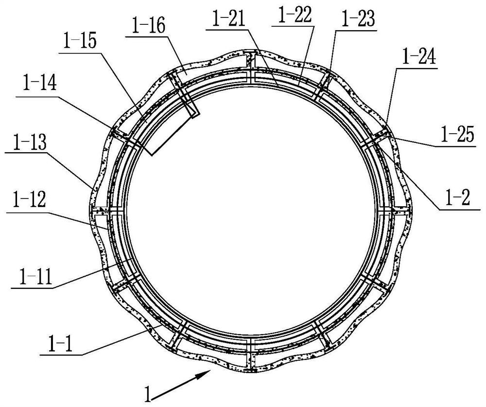
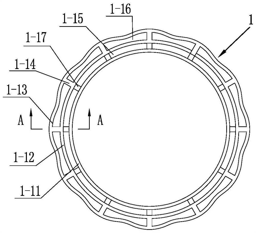
[0033] See Figure 1-13 As shown, the manufacturing method of the landscape interception well body of the present invention includes the following steps.

[0034] (1) Print well body components: use concrete 3D to print out a plurality of first well body components 1 for splicing, a plurality of second well body components 2 and well bottom components 3, and the concrete can be made of not less than C30 concrete Strong printing material.

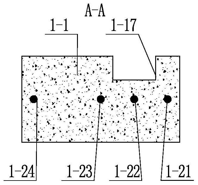
[0035] Make the first well body component 1, see Figure 1~3As shown, the first inner cover 1-11, the first outer cover 1-12 and the decorative ring 1-13 are printed from the inside to the outside with concrete 3D, and the first inner cover 1-11, the first outer cover 1-12 are connected The first well wall 1-1 composed of a plurality of first ribs 1-14 on the decorative ring 1-13, the first ribs 1-14 in pairs and the first inner sleeve 1-11 and the first outer sleeve 1-1 12 Form the first cavity for grouting and the overhead cavity 1-16 f...


PUM

PropertyMeasurementUnit
Heightaaaaaaaaaa

Abstract

The invention relates to a manufacturing method of a landscape intercepting well body. The manufacturing method comprises the following steps that (1) a plurality of first well body components, a plurality of second well body components and a well bottom component at the bottom are printed through concrete 3D, wherein the first well body components and the second well body components are used for splicing; (2) the well bottom component, the second well body components and the first well body components are spliced to the set height one by one from bottom to top, and all first cavities are kept to communicate with all second cavities; and (3) a plurality of vertical ribs are placed in the first cavities of the first well body components and the second cavities of the second well body components correspondingly and supported by the well bottom component, high-strength non-shrinkage grouting materials are poured into the first cavities and the second cavities, the first cavities, the second cavities, first concave parts and second concave parts are filled with the grouting materials, and the well bottom component, the second well body components and the first well body components are fixed and subjected to water stopping. According to the manufacturing method, the overall performance is good, the construction period is short, the appearance modeling is richer and more diverse, and transportation and civil engineering installation are greatly relieved.

Description

technical field [0001] The invention relates to a method for making a well body of a landscape interception well, and belongs to the technical field of urban rainwater pipeline systems. Background technique [0002] At present, the urban drainage pipe network system is generally divided into two types: combined drainage pipe network and divergent drainage pipe network. The combined drainage system has two main functions, one is to intercept sewage, so that the sewage entering the water body is as small as possible, and the other is to discharge floods in rainy days. The facilities that realize the above functions are called interception wells. However, in some scenes such as the historical and cultural blocks of the old city, there are requirements for the appearance of the interception well in the river. [0003] The well body of traditional interception well adopts ordinary reinforced concrete structure, which requires construction procedures such as pouring foundation, t...

Claims


Application Information

Patent Timeline
IPC IPC(8): E03F5/04E03F5/00B28B1/00B28B21/04B28B21/56B33Y10/00B33Y80/00
CPCY02A10/30
Inventor 谢文彬孙晓东孙晖杨云安蔚阳史文晶马珊
Owner 常州市君杰水务科技有限公司
Learn More