Low-temperature in-tank pump without balance mechanism

A technology of balancing mechanism and low temperature tank, applied in the direction of pumps, pump components, mechanical equipment, etc., can solve the problems of rotor stuck lock, damage, imbalance of balance mechanism, etc., achieve less friction pairs, reduce the risk of sticking, bearing positioning simple effect

Pending Publication Date: 2021-04-20
CNOOC GAS & POWER GRP +1
View PDF0 Cites 1 Cited by
  • Summary
  • Abstract
  • Description
  • Claims
  • Application Information

AI Technical Summary

Problems solved by technology

The increase of dynamic and static friction pairs in the rotor system will bring the risk of rotor sticking and locking
[0005] In addition, the medium conveyed by the pump in the low-temperature tank is a low-temperature and easy-to-gasify medium. When the pump is operating under abnormal conditions and part of the medium is gasified, it will cause pressure drop changes and make the balance mechanism unbalanced, resulting in dynamic and static contact of the balance parts, prompting shutdown and failure of the pump. damage

Method used


Image

  • Low-temperature in-tank pump without balance mechanism
  • Low-temperature in-tank pump without balance mechanism
  • Low-temperature in-tank pump without balance mechanism

Examples


Embodiment Construction

[0026]In order to make the objects, technical solutions, and advantages of the present invention, the technical solutions in the present invention will be clear and complete, and it is apparent that the described embodiments are intended to be in an embodiment of the invention, not all of the embodiments. Based on the embodiments in the present invention, those of ordinary skill in the art are protected by the present invention without making creative labor premises.

[0027]Unless otherwise defined, the technical term or scientific terminology used in the present invention should be understood by the usual significance of people who are of general skills in the art of the present invention. "First", "second" and similar words used in the present invention do not represent any order, quantity, or importance, but is only used to distinguish between different components. Similar words to "include" or "include", meaning that the elements or objects of the previously mentioned previously e...


PUM


Abstract

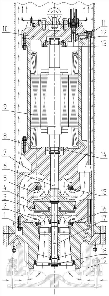
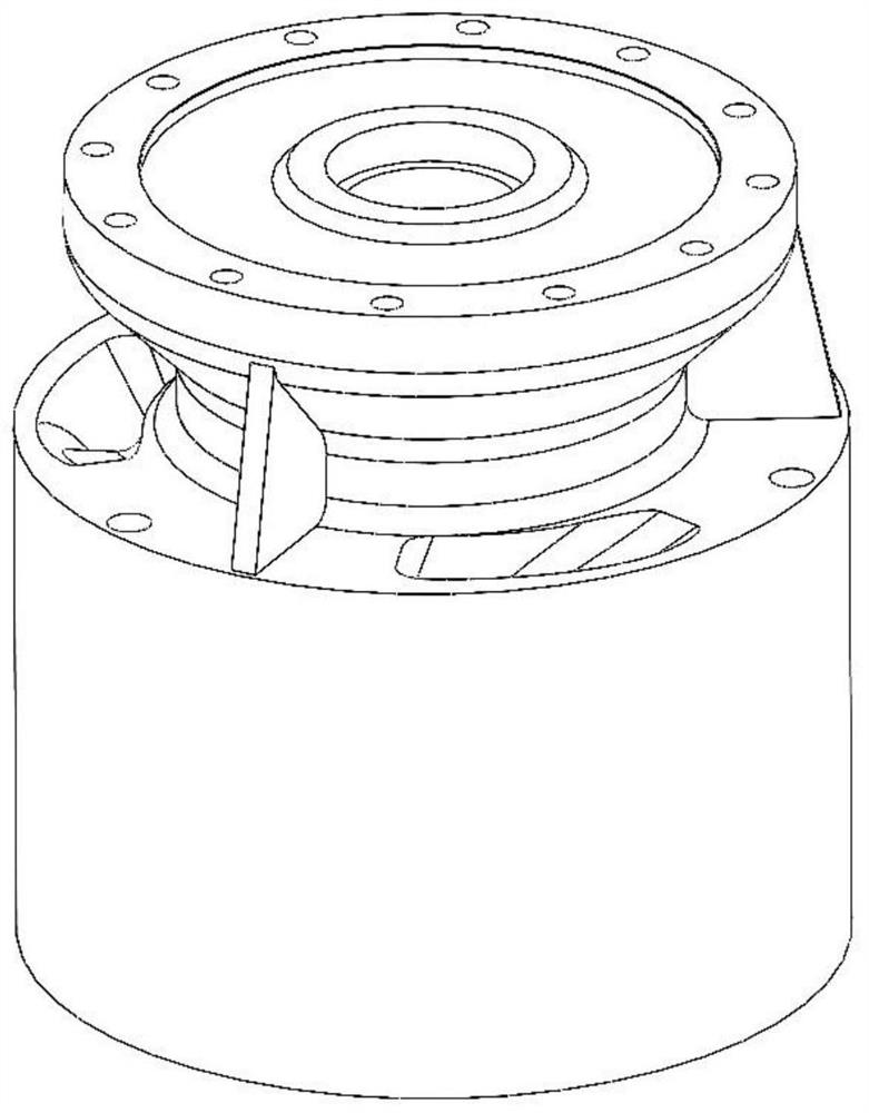
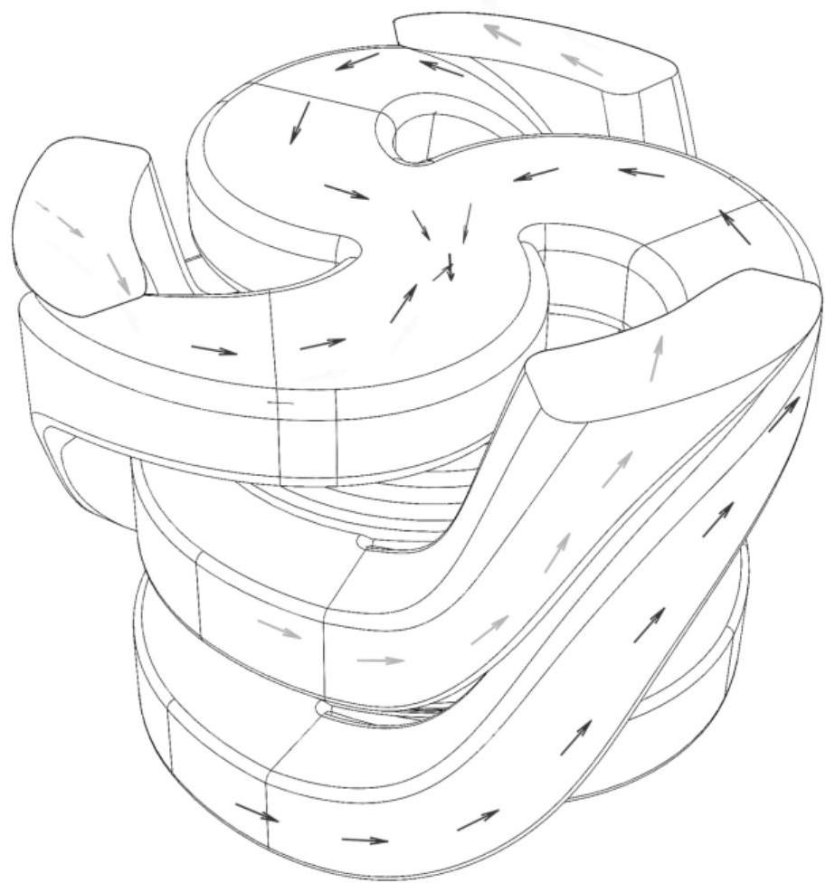
The invention relates to a low-temperature in-tank pump without a balance mechanism. The low-temperature in-tank pump without the balance mechanism comprises a spiral flow guide body, a rotating shaft and an inducer, wherein the spiral flow guide body is of a columnar structure; a cavity is arranged in the spiral flow guide body and is configured to accommodate a first-stage impeller and a secondary impeller; blades of the first-stage impeller and blades of the secondary impeller are arranged back to back; a first through hole and a plurality of overflow channels are further formed in the spiral flow guide body; the cavity is in fluid communication connection with the overflow channels; the rotating shaft penetrates through the first through hole; the first-stage impeller and the secondary impeller are annularly arranged on the rotating shaft in a sleeving mode; the first end of the rotating shaft is fixedly connected with a motor; the second end of the rotating shaft is a free end; and the inducer is annularly arranged at the second end of the rotating shaft in a sleeving mode and is configured to induce fluid to enter the spiral flow guide body. According to the low-temperature in-tank pump without the balance mechanism provided by the invention, the device is free of the balance mechanism, has the advantages of few friction pairs, simple bearing positioning and the like, is more suitable for conveying low-temperature easy-to-gasify media, and can be beneficial to greatly reducing the clamping stagnation risk of a pump rotor.

Description

Technical field[0001]The present invention relates to a low temperature tank of a balanced mechanism, belonging to a low temperature pump technology.Background technique[0002]There is a balance mechanism in the low temperature tank currently used, and the balancing mechanism uses a balance drum or a balanced disk, or the combination of the two. The principle of the balance mechanism is to balance the impeller axial force by using the pressure difference between the hydraulic pressure and the effect area.[0003]The establishment of the axial force balance is based on the direction of centrifugal pump, but the row of the center of the center changes with the flow rate, when the working point changes, the balanced position needs to be re-established, the balance mechanism gap will change, that is, the pump rotor will produce Make up. When the working condition changes quickly or starts and stops, the balance mechanism will inevitably produce grinding from the stationary parts due to ine...

Claims


Application Information

Patent Timeline
Patent Type & Authority Applications(China)
IPC IPC(8): F04D17/12F04D29/44F04D29/051F04D29/66
Inventor 明红芳张超陈海平许佳伟黄宇宋坤郭琦范嘉堃赖华山左广峰郝思佳刘福安龚洪伟倪乃坤冷志强苏幼明冷文
Owner CNOOC GAS & POWER GRP
Why Eureka
Try Eureka