Optical zoom system, camera module and electronic equipment

A technology of optical zoom and lens group, applied in optics, optical components, instruments, etc.

Pending Publication Date: 2021-04-20
JIANGXI JINGCHAO OPTICAL CO LTD
View PDF0 Cites 5 Cited by
  • Summary
  • Abstract
  • Description
  • Claims
  • Application Information

AI Technical Summary

Problems solved by technology

[0004] Based on this, it is necessary to provide an optical zoom system, a camera module and an ele

Method used


Image

  • Optical zoom system, camera module and electronic equipment
  • Optical zoom system, camera module and electronic equipment
  • Optical zoom system, camera module and electronic equipment

Examples


no. 1 example

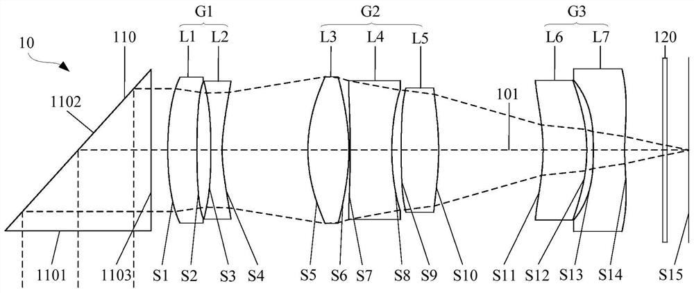
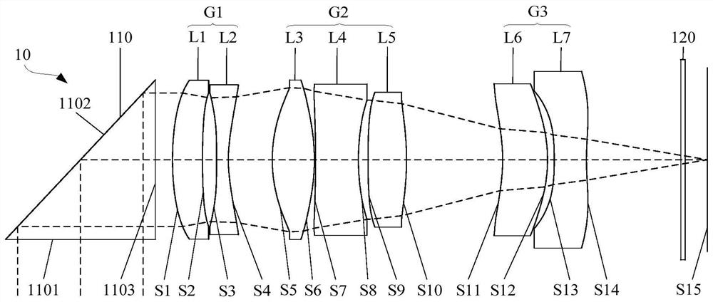
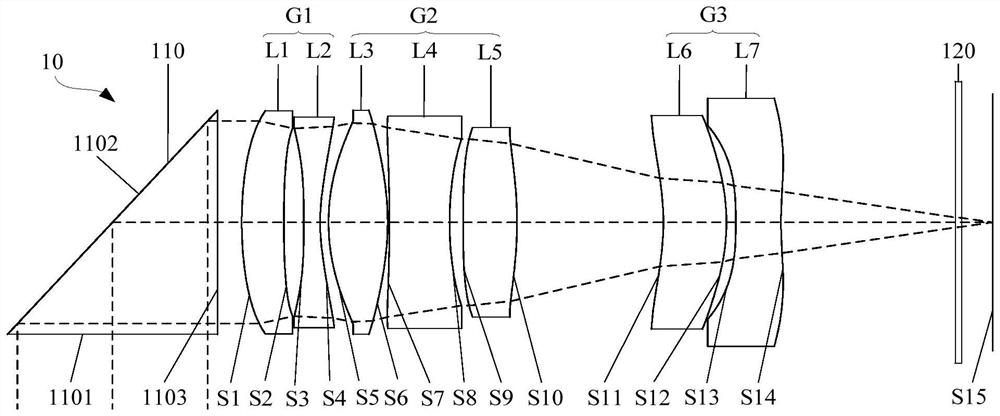
[0113] refer to figure 1 , figure 2 and image 3 , figure 1 It shows a schematic structural view of the optical zoom system 10 at the short-focus end, figure 2 It shows a schematic structural view of the optical zoom system 10 at the middle focal point, image 3 A schematic diagram of the structure of the optical zoom system 10 at the telephoto end is shown. It should be noted that, Figure 1 to Figure 3 The relative movement relationship between the lens groups during the zooming process of the system is given, but it does not mean that each system can only be adjusted between these three states, and the same is true for the following embodiments.

[0114] In the first embodiment, the optical zoom system 10 sequentially includes along the incident optical path: a reflective element 110 (a rectangular prism in the table below), a first mirror group G1 with negative refractive power, wherein the first mirror group G1 includes The first lens L1 with strong power and the ...

no. 2 example

[0145] refer to Figure 7 to Figure 9 , Figure 7 It shows a schematic structural view of the optical zoom system 10 at the short-focus end, Figure 8 It shows a schematic structural view of the optical zoom system 10 at the middle focal point, Figure 9 A schematic diagram of the structure of the optical zoom system 10 at the telephoto end is shown.

[0146] In the second embodiment, the optical zoom system 10 sequentially includes along the incident light path: a reflective element 110, a first lens group G1 with a negative refractive power, wherein the first lens group G1 includes a first lens L1 with a positive refractive power and a first lens L1 with a The second lens L2 with negative refractive power; the second lens group G2 with positive refractive power, wherein the second lens group G2 includes the third lens L3 with positive refractive power, the fourth lens L4 with negative refractive power, and the fourth lens L4 with positive refractive power and a third lens...

no. 3 example

[0168] refer to Figure 13 to Figure 15 , Figure 13 It shows a schematic structural view of the optical zoom system 10 at the short-focus end, Figure 14 It shows a schematic structural view of the optical zoom system 10 at the middle focal point, Figure 15 A schematic diagram of the structure of the optical zoom system 10 at the telephoto end is shown.

[0169] In this embodiment, the optical zoom system 10 sequentially includes along the incident optical path: a reflective element 110, a first lens group G1 with negative refractive power, wherein the first lens group G1 includes a first lens L1 with positive refractive power and a first lens L1 with negative refractive power. A second lens L2 with a refractive power; a second lens group G2 with a positive refractive power, wherein the second lens group G2 includes a third lens L3 with a positive refractive power, a fourth lens L4 with a negative refractive power, and a fourth lens L4 with a positive refractive power and...


PUM


Abstract

The invention relates to an optical zoom system, a camera module and electronic equipment. The optical zoom system includes: a first lens group having negative refractive power and including a first lens and a second lens; a second lens group having positive refractive power and including a third lens, a fourth lens, and a fifth lens; and a third lens group having negative refractive power and including a sixth lens and a seventh lens. In the zooming process from the short-focus end to the long-focus end, the distance between the first lens group and the second lens group is reduced, and the distance between the third lens group and the imaging surface is increased; the system satisfies the following relationship: 0.2 < (R5-R6)/R8 < 3; and R5 is the curvature radius of the object side surface of the third lens at the optical axis, R6 is the curvature radius of the image side surface of the third lens at the optical axis, and R8 is the curvature radius of the image side surface of the fourth lens at the optical axis. The optical zoom system satisfying the above relationship is beneficial for enabling the aberration component between the lens groups to reach a balanced state, thereby being beneficial for improving the imaging quality.

Description

technical field [0001] The invention relates to the technical field of photography and imaging, in particular to an optical zoom system, a camera module and electronic equipment. Background technique [0002] With the development of camera technology, the camera module has gradually developed from a fixed-focus system with relatively limited camera conditions to a zoom system that can switch between different camera conditions. The zoom design can make the system change correspondingly in parameters such as focal length, field of view, aperture number, etc., so that it can have the function of switching between the long-focus end and the short-focus end, and then can adapt to certain imaging quality while ensuring certain imaging quality. Different camera requirements such as object distance, depth of field, shooting range, etc. [0003] But generally, with the relative movement between some lenses in the zoom system, the aberrations generated by the lens or the lens group ...

Claims


Application Information

Patent Timeline
IPC IPC(8): G02B15/177G02B15/14
Inventor 杨健李明
Owner JIANGXI JINGCHAO OPTICAL CO LTD
Why Eureka
Try Eureka