
Quantitative characterization method and system for seepage interface of water-drive reservoir flow unit

A technology of flow unit and quantitative characterization, which is applied in the direction of production fluid, earthwork drilling and production, wellbore/well components, etc., can solve the problems that cannot be used to study the distribution of underground oil and water, predict the distribution of remaining oil, and do not consider the flow field velocity and saturation changes over time, etc.

Active Publication Date: 2021-04-20
CHINA PETROLEUM & CHEM CORP
View PDF12 Cites 0 Cited by
  • Summary
  • Abstract
  • Description
  • Claims
  • Application Information

AI Technical Summary

Problems solved by technology

[0004] In summary, the existing methods focus on dividing the flow unit by static parameters, without considering the change of flow field velocity and saturation over time, and cannot characterize the seepage interface of the flow unit changing at different times, and can only be used to predict the remaining oil. It cannot be used to study the distribution law of underground oil and water and the distribution prediction of remaining oil

Method used


Image

  • Quantitative characterization method and system for seepage interface of water-drive reservoir flow unit
  • Quantitative characterization method and system for seepage interface of water-drive reservoir flow unit
  • Quantitative characterization method and system for seepage interface of water-drive reservoir flow unit

Examples


Embodiment Construction

[0092] The following will clearly and completely describe the technical solutions in the embodiments of the present invention with reference to the accompanying drawings in the embodiments of the present invention. Obviously, the described embodiments are only some, not all, embodiments of the present invention. Based on the embodiments of the present invention, all other embodiments obtained by persons of ordinary skill in the art without making creative efforts belong to the protection scope of the present invention.

[0093] The purpose of the present invention is to provide a quantitative characterization method and system for the flow unit seepage interface of a water drive reservoir, which can quantitatively characterize the dynamic seepage interface of the water drive oil process, and quantitatively describe the evolution process of the flow unit seepage interface of the water drive reservoir, thereby accurately Determine the oil-water distribution.

[0094] In order to...


PUM


Abstract

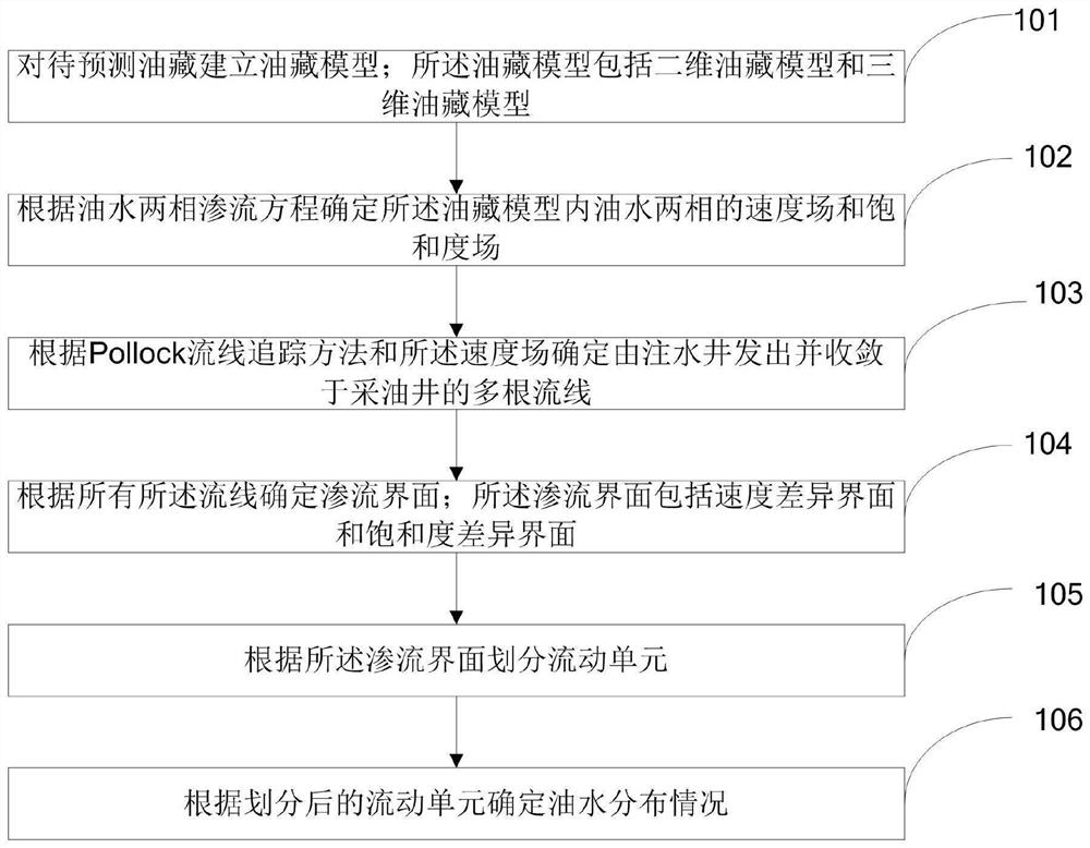
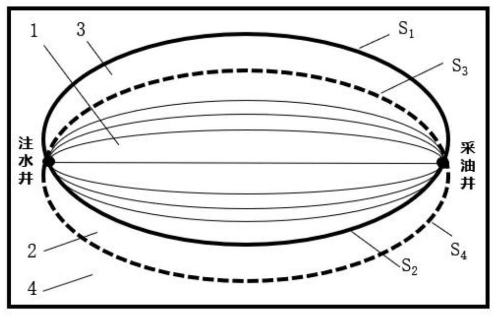
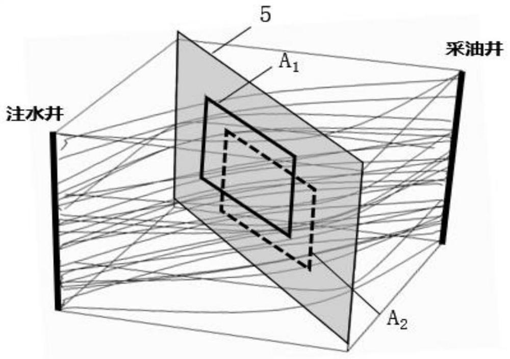
The invention discloses a quantitative characterization method and system for a seepage interface of a water-drive reservoir flow unit, and relates to the technical field of oilfield exploitation.The method comprises: establishing an oil reservoir model for a to-be-predicted oil reservoir, wherein the oil reservoir model comprises a two-dimensional oil reservoir model and a three-dimensional oil reservoir model; determining a velocity field and a saturation field of the oil-water two phases in the oil reservoir model according to an oil-water two-phase seepage equation; according to a Pollock streamline tracking method and the velocity field, determining a plurality of streamlines which are sent by the water injection well and converge to the oil production well; determining a seepage interface according to all the streamlines, wherein the seepage interface comprises a speed difference interface and a saturation difference interface; dividing a flow unit according to the seepage interface; and determining the oil-water distribution condition according to the divided flow units. The method and system can quantitatively characterize the dynamic seepage interface of the water-drive oil reservoir process and quantitatively describe the evolution process of the seepage interface of the water-drive oil reservoir flow unit, so that the oil-water distribution condition is accurately determined.

Description

technical field [0001] The invention relates to the technical field of oilfield exploitation, in particular to a method and system for quantitatively characterizing seepage interfaces of flow units in water drive reservoirs. Background technique [0002] Most of my country's oilfields are mainly exploited by water injection. In the stage of ultra-high water-cut development, due to long-term water injection erosion, the heterogeneity of the formation structure is enhanced, and the geological conditions are extremely complex, so that different laws of injected water movement will be formed in the oil layer. , water flooding characteristics and displacement degree, the difference in oil-water flow in the reservoir and the phenomenon of dispersion and enrichment of remaining oil are becoming more and more serious, which will eventually lead to the difficulty of remaining oil recovery. Research and finely describe the flow process of oil-water two phases in the formation, which can...

Claims


Application Information

Patent Timeline
IPC IPC(8): G06F30/28E21B43/20G06F111/10G06F113/08
CPCY02A10/40
Inventor 段欣悦孙康松巩亮黄朝琴胡慧芳
Owner CHINA PETROLEUM & CHEM CORP
Learn More