
Method for improving precision of ion implantation machine

An ion implantation and machine technology, which is used in the manufacture of discharge tubes, electrical components, semiconductor/solid-state devices, etc., can solve problems such as mismatching SIMS results of secondary ion mass spectrometry

Active Publication Date: 2021-04-20
SHANGHAI HUALI INTEGRATED CIRCUTE MFG CO LTD
View PDF6 Cites 0 Cited by
  • Summary
  • Abstract
  • Description
  • Claims
  • Application Information

AI Technical Summary

Problems solved by technology

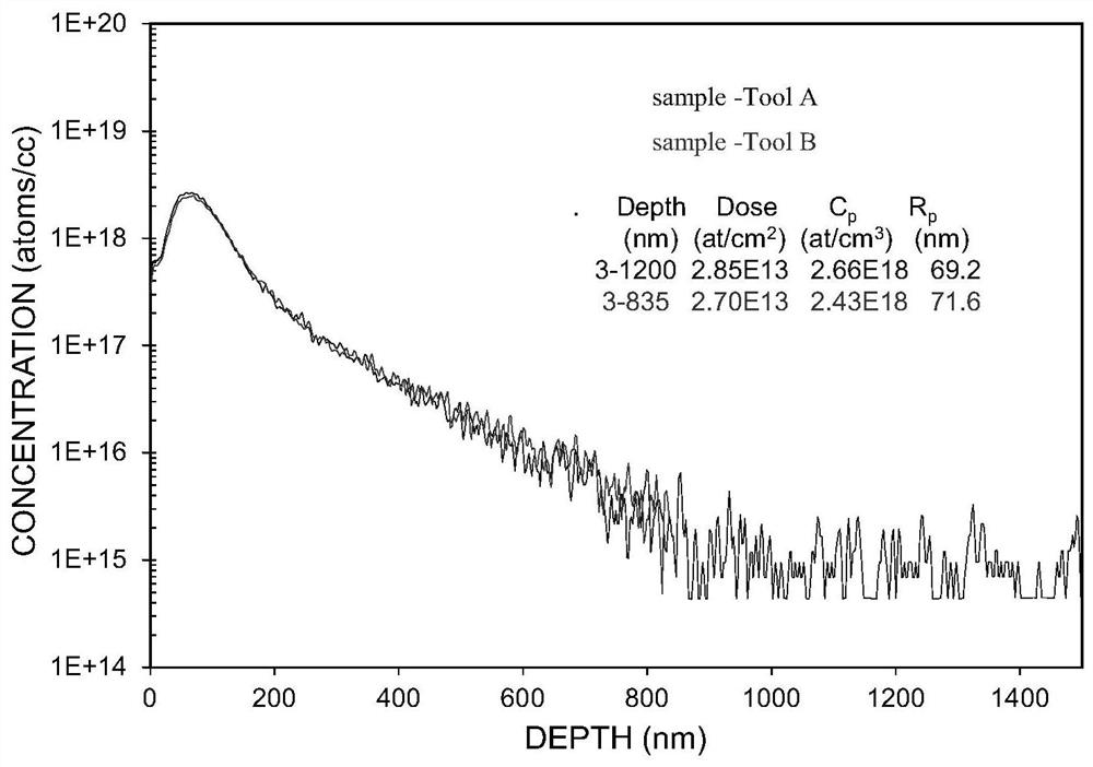
[0004] In view of the shortcomings of the prior art described above, the purpose of the present invention is to provide a method for improving the accuracy of the ion implantation machine, which is used to solve the problem of matching the sheet resistance of the ion implantation machine and the reference machine verified in the prior art. In some cases, the SIMS results of the two secondary ion mass spectrometers do not match

Method used


Image

  • Method for improving precision of ion implantation machine
  • Method for improving precision of ion implantation machine
  • Method for improving precision of ion implantation machine

Examples


Embodiment Construction

[0026] Embodiments of the present invention are described below through specific examples, and those skilled in the art can easily understand other advantages and effects of the present invention from the content disclosed in this specification. The present invention can also be implemented or applied through other different specific implementation modes, and various modifications or changes can be made to the details in this specification based on different viewpoints and applications without departing from the spirit of the present invention.

[0027] see Figure 1 to Figure 4 . It should be noted that the diagrams provided in this embodiment are only schematically illustrating the basic idea of ​​the present invention, and only the components related to the present invention are shown in the diagrams rather than the number, shape and shape of the components in actual implementation. Dimensional drawing, the type, quantity and proportion of each component can be changed arb...


PUM


Abstract

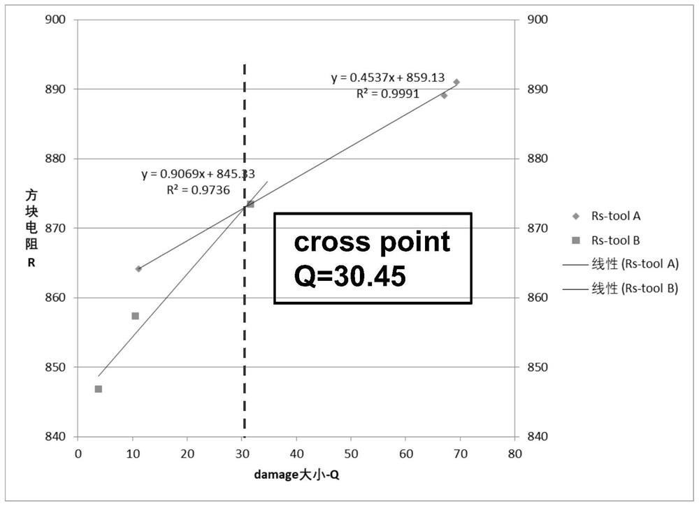
The invention provides a method for improving the precision of an ion implantation machine. The method comprises the following steps: carrying out a square resistance Rs test by utilizing a reference machine; performing a square resistance sensitivity test on a verified machine; testing a square resistance difference value between the reference machine table and the verified machine under the same test condition, and matching the square resistance Rs of the verified machine with the square resistance Rs of the reference machine by performing dosage fine adjustment of ion implantation on the verified machine; defining a relative damage degree Q of ion implantation, obtaining a curve that the square resistance Rs value changes along with Q according to the relationship between the Q values of the reference machine and the verified machine and the square resistance Rs, and calculating the Rs and Q values corresponding to the intersection point of the curve; finely adjusting test conditions of the reference machine and the verified machine to obtain injection programs corresponding to curve intersection points Rs and Q values; and verifying whether the secondary ion mass spectrum SIMS results of the reference machine and the verified machine are matched or not by utilizing secondary ion mass spectrum analysis.

Description

technical field [0001] The invention relates to the technical field of semiconductors, in particular to a method for improving the precision of an ion implantation machine. Background technique [0002] In the prior art, it is necessary to match the verified ion implantation machine with the reference machine. Usually, a sensitivity test is performed on the verified machine first, and then the actual difference in sheet resistance Rs of the two models is calculated (generally considered as the difference in Rs It comes from the difference in the actual dose of the two models), Rs matching can be achieved by modifying the dose trim, and finally sent to the secondary ion mass spectrometer (SIMS) to confirm whether the ion implantation form matches. But for some test programs (recipes), Rs matching can be achieved by modifying the dose trim, but the SIMS morphology does not match. [0003] Therefore, a new method needs to be proposed to solve the above-mentioned problems. Co...

Claims


Application Information

Patent Timeline
IPC IPC(8): H01J37/317H01L21/67
Inventor 周真真刘厥扬胡展源
Owner SHANGHAI HUALI INTEGRATED CIRCUTE MFG CO LTD
Learn More