Eureka AIR delivers breakthrough ideas for toughest innovation challenges, trusted by R&D personnel around the world.

Patch positioning jig for ceramic substrate on optical device and optical device packaging method

A ceramic substrate and positioning jig technology, applied in laser parts, lasers, semiconductor lasers, etc., can solve the problems of complex process and high price, and achieve the effect of simple operation, low production cost and low cost

Pending Publication Date: 2021-04-20
LITUREX GUANGZHOU CO LTD
View PDF0 Cites 0 Cited by
  • Summary
  • Abstract
  • Description
  • Claims
  • Application Information

AI Technical Summary

Problems solved by technology

Therefore, special equipment is specially designed to do eutectic welding in the prior art, which is expensive and complicated.

Method used


Image

  • Patch positioning jig for ceramic substrate on optical device and optical device packaging method
  • Patch positioning jig for ceramic substrate on optical device and optical device packaging method
  • Patch positioning jig for ceramic substrate on optical device and optical device packaging method

Examples


Embodiment Construction

[0034] In order to describe the technical content, structural features, and achieved effects of the present invention in detail, the following will be described in detail in conjunction with the embodiments and accompanying drawings.

[0035] In describing the present invention, it is to be understood that the terms "upper", "lower", "bottom", "top", "inner", "outer", "front", "back", "horizontal", The orientation or positional relationship indicated by "vertical" is based on the orientation or positional relationship shown in the drawings, and is only for the convenience of describing the present invention and simplifying the description, and thus cannot be construed as limiting the protection content of the present invention.

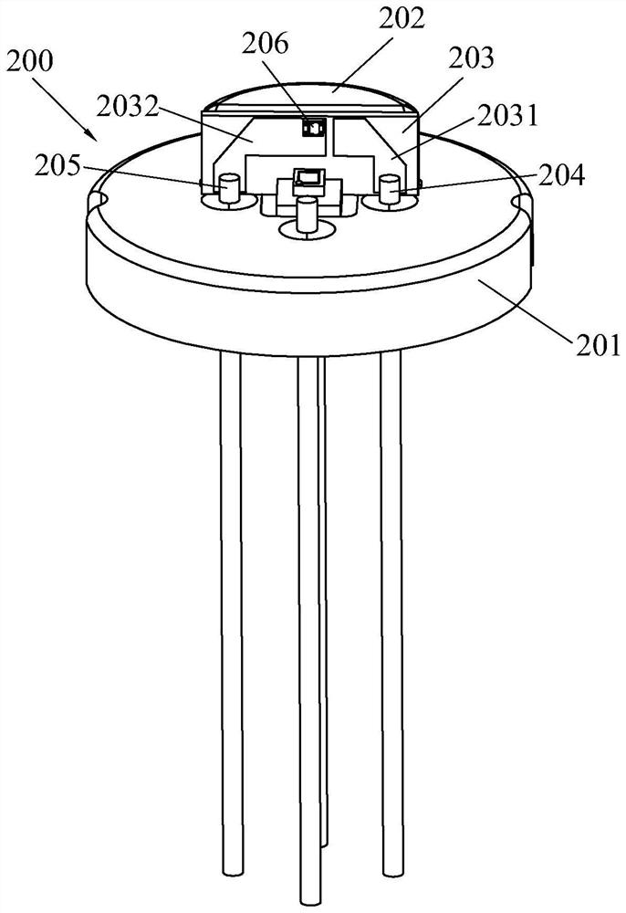
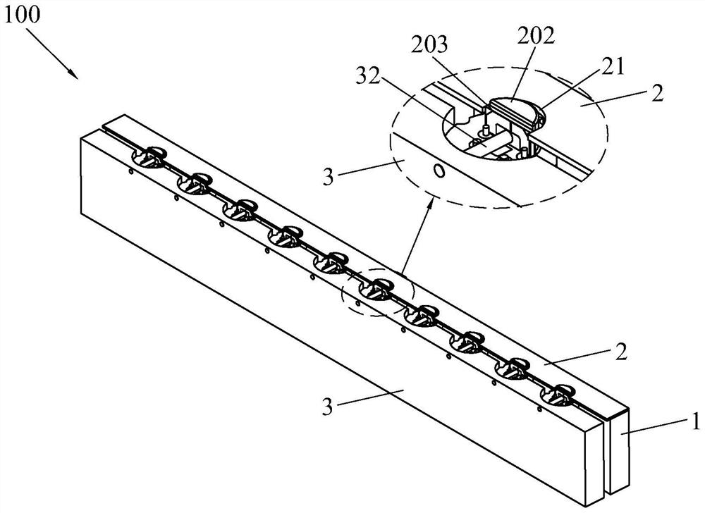
[0036] The present invention discloses an optical device ceramic substrate patch positioning jig 100, which is used for positioning the optical device 200 so as to realize high-frequency signal lines 2031, 2032 on the ceramic substrate 203 and high-fre...


PUM

PropertyMeasurementUnit
melting pointaaaaaaaaaa

Abstract

The invention discloses a patch positioning jig for a ceramic substrate on an optical device. The positioning jig comprises a tube socket positioning piece, a substrate limiting piece and a substrate flattening piece, wherein the tube socket positioning piece is provided with a plurality of placing grooves for placing optical devices; the substrate limiting piece is provided with a plurality of limiting parts, each limiting part corresponds to one placing groove, and the offset of the ceramic substrate in a horizontal direction is limited through the substrate limiting piece so as to control the patch position precision of the ceramic substrate; and the substrate flattening piece comprises a plurality of abutting pieces, and acting force perpendicular to a heat sink is applied to the ceramic substrate through the abutting pieces, so the ceramic substrate is tightly attached to the heat sink, a structure is simple, and cost is low. In addition, the invention also discloses an optical device packaging method. According to the invention, the positioning of the optical device and the precise control of the patch position of the ceramic substrate are realized through the positioning jig; and the positioning jig is placed on an existing dispensing machine for dispensing, then the positioning jig is heated through heating equipment to melt gold soldering paste, then eutectic soldering of a high-frequency signal pin and a high-frequency signal line is completed, and operation is easy.

Description

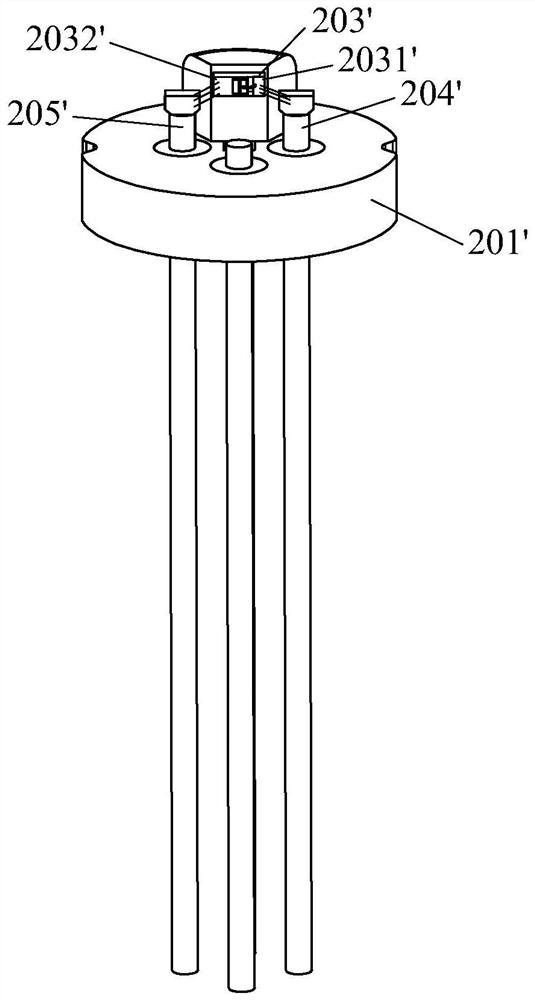
technical field [0001] The invention relates to the technical field of high-speed optical device packaging, in particular to a positioning jig for optical device ceramic substrate patch and an optical device packaging method. Background technique [0002] 25G and 50G optical modules are used in the 5G optical communication network. Due to the high transmission rate of the laser, in order to ensure signal integrity, it is necessary to ensure ultra-low signal insertion loss and reflection throughout the transmission link. In traditional 10G and below 10G optical device packages, the high-frequency signal lines 2031', 2032' on the ceramic substrate 203' and the high-frequency signal pins 204 on the TO56 socket 201' are all connected by gold wires. ', 205' for electrical connection (such as figure 1 shown). This method has the problems of large parasitic inductance and impedance mismatch. When applied to high-speed signal transmission, the reflection and insertion loss will be...

Claims


Application Information

Patent Timeline
Patent Type & Authority Applications(China)
IPC IPC(8): H01S5/02315H01S5/02325H01S5/0237H01S5/02375H01S5/024
Inventor 李海坚宋云鹏
Owner LITUREX GUANGZHOU CO LTD
Why Eureka
Eureka Blog
Learn More