Rotor structure of large-shaft-diameter built-in permanent magnet motor and motor thereof

A permanent magnet motor and rotor structure technology, applied in the direction of magnetic circuit shape/style/structure, winding conductor shape/style/structure, magnetic circuit rotating parts, etc., can solve the problem of increasing the radial thickness of the rotor, etc., to achieve Effects of reducing erosion, increasing sine degree, and improving space utilization

Pending Publication Date: 2021-04-20
NINGBO INST OF MATERIALS TECH & ENG CHINESE ACADEMY OF SCI
View PDF1 Cites 2 Cited by
  • Summary
  • Abstract
  • Description
  • Claims
  • Application Information

AI Technical Summary

Problems solved by technology

The structure of the permanent magnet in the rotor is still "inline", so the magnetic potential waveform generated by the permanent magnet does not change. At the same time, the rotor structure also increases the radial thickness of the rotor, which is not suitable for the working condition of large shaft diameter

Method used


Image

  • Rotor structure of large-shaft-diameter built-in permanent magnet motor and motor thereof
  • Rotor structure of large-shaft-diameter built-in permanent magnet motor and motor thereof
  • Rotor structure of large-shaft-diameter built-in permanent magnet motor and motor thereof

Examples


Embodiment Construction

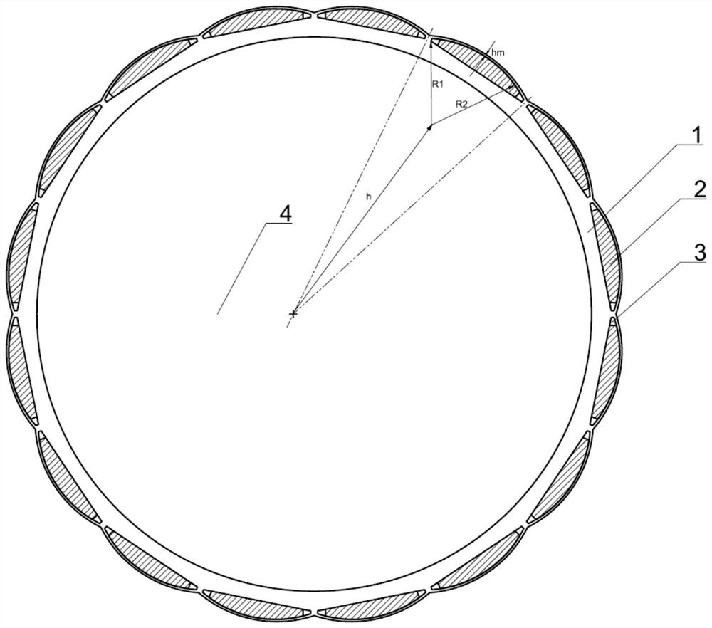
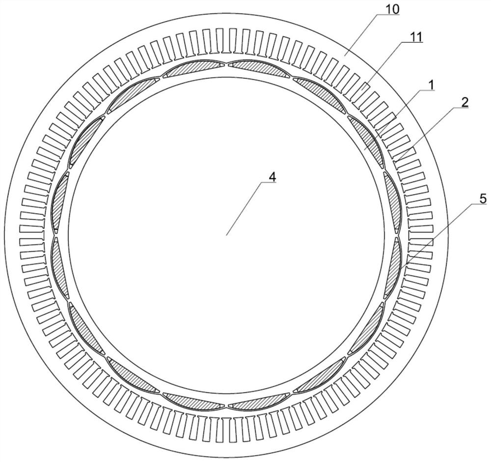
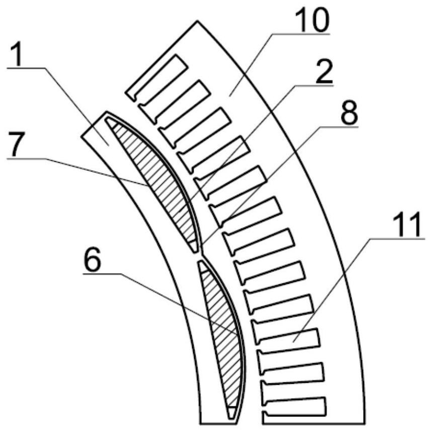
[0032] Such as figure 1 , 4 As shown, the rotor structure of the large shaft diameter built-in permanent magnet motor includes a rotor core 1; 16 (p=8) semi-shuttle-shaped magnetic steel grooves 3 are evenly distributed inside the rotor core 1 along the circumferential direction, and the magnetic steel grooves are circular. The arc surface 6 is a semi-shuttle-shaped arc edge, and the semi-shuttle-shaped arc edge takes the point near the arc direction and the center of the rotor core 1 as h as the center of the circle, and the length R 1 Be radius, magnetic steel groove bottom surface 7 is the straight edge of half shuttle.

[0033] The inside of the magnetic steel slot 3 is fixed with a semi-shuttle permanent magnet 2, and the arc surface of the semi-shuttle permanent magnet 2 is at the same position as the center of the arc surface 6 of the magnetic steel slot and has the same radius; The eccentric arc parallel to the groove arc surface 6, the eccentric arc is concentric wi...


PUM


Abstract

The invention discloses a rotor structure of a large-shaft-diameter built-in permanent magnet motor. The rotor structure comprises a rotor core; 2p semi-fusiform magnetic steel grooves are uniformly formed in the rotor core in the circumferential direction, wherein p is the number of pole pairs; each magnetic steel groove arc surface is a semi-fusiform arc edge, the point of the semi-fusiform arc edge close to the arc direction and away from the circle center h of the rotor core is used as the circle center, the length R1 is used as the radius, and each magnetic steel groove bottom surface is a semi-fusiform straight edge. Semi-fusiform permanent magnets are fixed in the magnetic steel grooves, and the arc surfaces of the semi-fusiform permanent magnets and the arc surfaces of the magnetic steel grooves are the same in circle center position and equal in radius; and the outer surface of the rotor core is an eccentric arc parallel to the arc surfaces of the magnetic steel grooves. By adopting the rotor structure of the large-shaft-diameter built-in permanent magnet motor, vibration and noise generated by the motor can be reduced under the condition that the performance of the motor is not lost, the radial thickness of the rotor core is reduced, and the space utilization rate of the rotor structure is improved.

Description

technical field [0001] The invention relates to the technical field of permanent magnet motors, in particular to a rotor structure of a large shaft diameter built-in permanent magnet motor and the motor thereof. Background technique [0002] The no-load back EMF of the permanent magnet synchronous motor refers to the induced electromotive force generated by the no-load air-gap flux in the armature winding when the current of the armature winding is zero. The no-load back EMF and air gap magnetic density generated by a permanent magnet synchronous motor with a uniform air gap are approximately flat-top waves, and its waveform distortion rate is high, and the air gap magnetic field contains a large number of harmonics. If the structure design of the rotor and permanent magnet is unreasonable, greater harmonic content and torque fluctuation will be generated, resulting in additional vibration and noise of the motor, reducing the efficiency and service life of the motor. [000...

Claims


Application Information

Patent Timeline
Patent Type & Authority Applications(China)
IPC IPC(8): H02K1/27H02K3/12H02K3/28
Inventor 陈进华赵士豪张驰高云鹏蒋哲
Owner NINGBO INST OF MATERIALS TECH & ENG CHINESE ACADEMY OF SCI
Why Eureka
Try Eureka