Signal real-time monitoring method, system, electronic device and storage medium

A real-time monitoring system and real-time detection technology, applied in the direction of transmission system, digital transmission system, electrical components, etc., can solve the problem of not being able to relieve the patient's dangerous situation in time, making a treatment plan, and can only be fixed in the hospital and cannot move at will. , to achieve the effect of facilitating timely diagnosis and treatment of diseases

Active Publication Date: 2021-07-02
SOUTH SUZHOU MEDICAL TECH CO LTD
View PDF0 Cites 0 Cited by
  • Summary
  • Abstract
  • Description
  • Claims
  • Application Information

AI Technical Summary

Problems solved by technology

[0002] With the development of technology, the size of ECG monitoring equipment is becoming more and more portable, from the large monitoring equipment that can only be fixed in the hospital and cannot be moved at will, to the Holter, commonly known as the "back box", to smaller and more Wearable ECG monitoring equipment that is easier to carry around. The evolution of the equipment, especially the portability, means that the patient's ECG signal can be monitored for a longer period of time, and it will not bring additional burden to the patient and affect the normal life of the patient. In order to restore the patient's routine activities during the monitoring or diagnosis process, and make the detection more accurate, but the stored data of the wearable ECG monitoring device in the prior art needs to be stopped and sent to the doctor for analysis, and the doctor cannot use the patient's ECG. Abnormal timely and targeted treatment plan, unable to relieve the patient's dangerous situation in time

Method used


Image

  • Signal real-time monitoring method, system, electronic device and storage medium
  • Signal real-time monitoring method, system, electronic device and storage medium
  • Signal real-time monitoring method, system, electronic device and storage medium

Examples


Embodiment 1

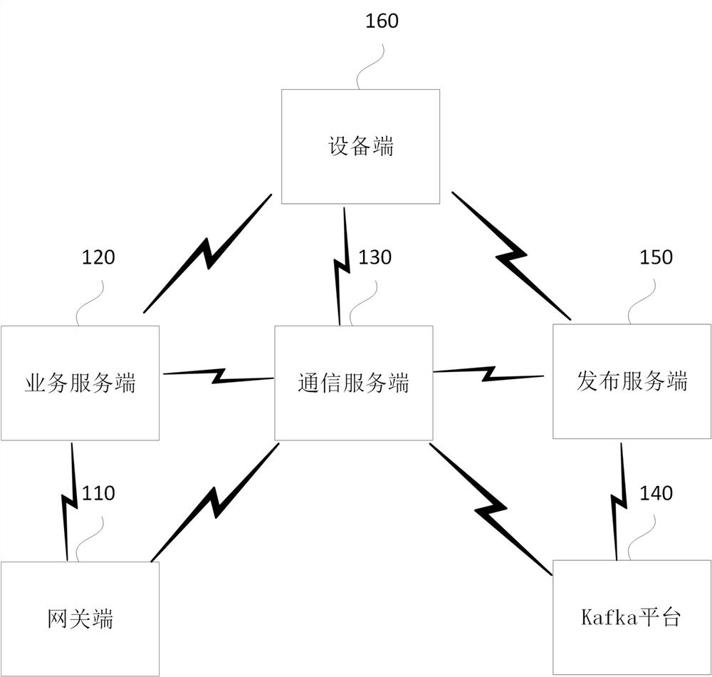
[0032] figure 1 It is a schematic structural diagram of a real-time signal monitoring system provided by Embodiment 1 of the present invention. This embodiment is applicable to the situation of real-time monitoring of physiological signals of target users. Such as figure 1 As shown, the system specifically includes: at least one gateway end 110, business server end 120, communication server end 130, Kafka platform 140, publishing server end 150 and at least one device end 160, wherein:

[0033] The gateway end 110 is configured to obtain the real-time detection signal of the target object collected by the signal detection end.

[0034] The business server 120 is connected to the gateway 110 and the device 160 respectively, and is used to receive the order creation instruction transmitted by the device 160, and create a signal detection order of the target object according to the order creation instruction. The signal detection order carries gateway information and Device Inf...

Embodiment 2

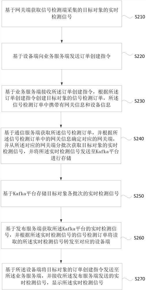
[0058] figure 2 It is a schematic flowchart of the method for real-time signal monitoring provided by Embodiment 2 of the present invention. This embodiment is applicable to the situation of real-time monitoring of physiological signals of target users. The method can be executed by the signal real-time monitoring system provided in the above embodiments, and the system can be implemented by software and / or hardware.

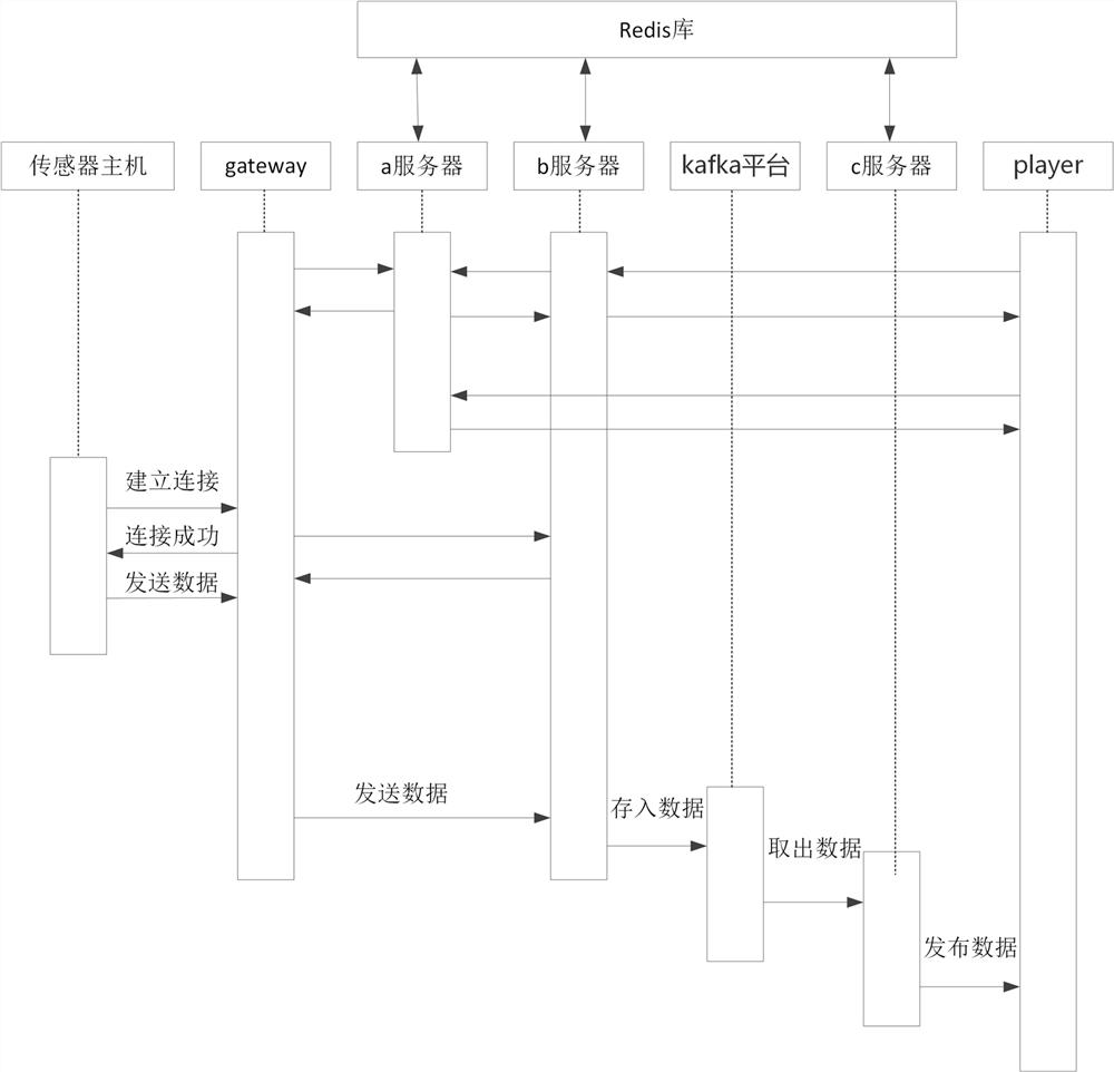
[0059] Before implementing the technical solution of this embodiment, the gateway end and the device end in the signal real-time monitoring system in the above embodiment are respectively established to communicate with the communication server end, so that the signal can be transmitted in real time. Specifically: the device side can use the preset account to log in when it is turned on, so that the device side can create an order creation instruction according to the target object after logging in, and establish a Netty communication connection with the commun...

Embodiment 3

[0098] Figure 4 It is a schematic structural diagram of an electronic device provided by Embodiment 3 of the present invention. Figure 4 A block diagram of an exemplary electronic device 12 suitable for use in implementing embodiments of the invention is shown. Figure 4 The electronic device 12 of the device is just an example and should not limit the functions and scope of use of the embodiments of the present invention.

[0099] Such as Figure 4 As shown, electronic device 12 takes the form of a general computing electronic device. Components of electronic device 12 may include, but are not limited to: one or more processors or processing units 16 , system memory 28 , bus 18 connecting various system components (including system memory 28 and processing unit 16 ).

[0100] Bus 18 represents one or more of several types of bus structures, including a memory bus or memory controller, a peripheral bus, an accelerated graphics port, a processor, or a local bus using any o...


PUM


Abstract

The embodiment of the invention discloses a signal real-time monitoring method, system, electronic equipment and storage medium. The method includes: obtaining the real-time detection signal of the target object collected by the signal detection end; based on the order creation instruction received by the business server, creating a signal detection order of the target object according to the order creation instruction; obtaining the signal detection order, and according to the signal detection order. The gateway information determines the corresponding gateway end, and obtains the real-time detection signal of the target object in batches from the corresponding gateway end, and sends the real-time detection signal to the Kafka platform for storage; obtains the real-time detection signal of the Kafka platform, and according to the real-time detection signal The signal detection order forwards the read real-time detection signal to the corresponding device end; sends the order creation instruction of the target object to the business server, and receives the real-time detection signal sent by the release server, and displays the real-time detection signal. Real-time display of monitoring data is realized through the technical solutions of the embodiments of the present invention.

Description

technical field [0001] Embodiments of the present invention relate to the technical field of physiological feature monitoring, and in particular, to a signal real-time monitoring method, system, electronic equipment, and storage medium. Background technique [0002] With the development of technology, the size of ECG monitoring equipment is becoming more and more portable, from the large monitoring equipment that can only be fixed in the hospital and cannot be moved at will, to the Holter, commonly known as the "back box", to smaller and more Wearable ECG monitoring equipment that is easier to carry around. The evolution of the equipment, especially the portability, means that the patient's ECG signal can be monitored for a longer period of time, and it will not bring additional burden to the patient and affect the normal life of the patient. In order to restore the routine activities of the patient during the monitoring or diagnosis process, and make the detection more accu...

Claims


Application Information

Patent Timeline
Patent Type & Authority Patents(China)
IPC IPC(8): H04L12/26
Inventor 高林明范哲权孙政
Owner SOUTH SUZHOU MEDICAL TECH CO LTD
Why Eureka
Try Eureka