Efficient PCB dust removal device for LED production
A dust removal device and PCB board technology, applied in cleaning methods and appliances, cleaning methods using liquids, chemical instruments and methods, etc., can solve the problems of inability to automatically unload materials, low efficiency of dust removal work, and high cost, so as to improve efficiency, Reduce the cost of dust removal and prolong the service life
- Summary
- Abstract
- Description
- Claims
- Application Information
AI Technical Summary
Problems solved by technology
Method used
Image
Examples
Embodiment 1
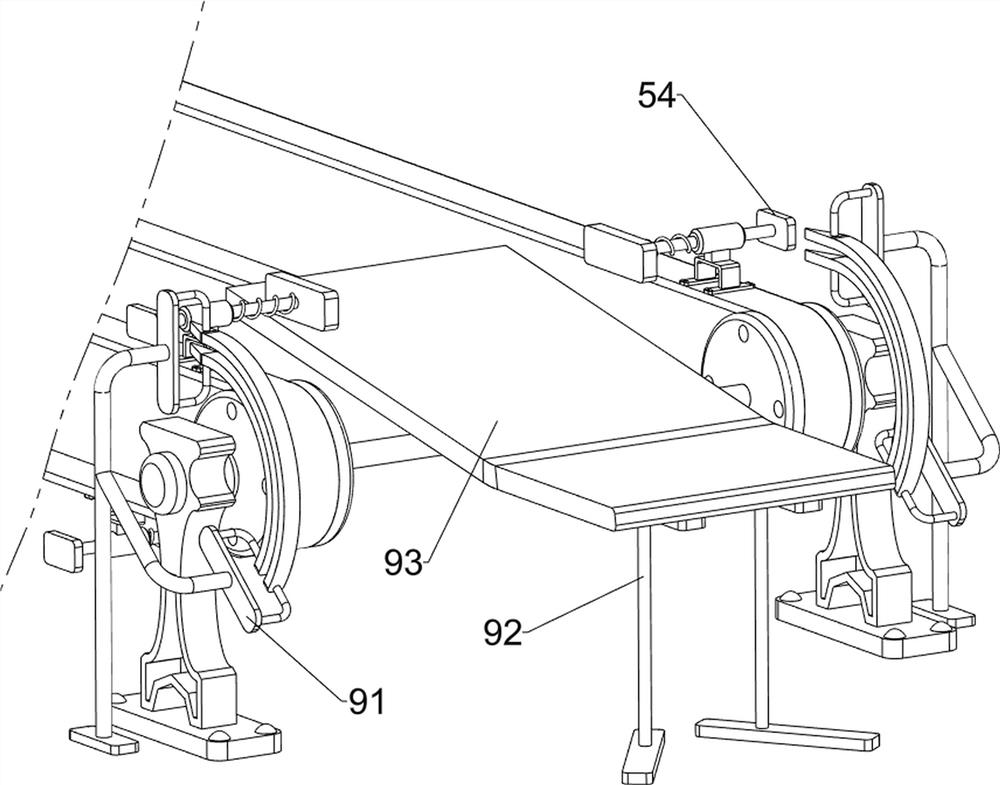
[0065] A kind of high-efficiency dust removal device for PCB board used in LED production, such as figure 1 , figure 2 and image 3 As shown, it includes a base plate 1, a bracket 2, a motor 3, a pressurized spraying mechanism 4 and a transmission clamping mechanism 5. A bracket 2 is provided on the front side of the upper right part of the base plate 1, and a motor 3 is installed on the top of the bracket 2. The upper middle part of the base plate 1 A pressurized spraying mechanism 4 is provided, and a transmission clamping mechanism 5 is provided on the upper middle of the bottom plate 1, and the transmission clamping mechanism 5 is connected with the output shaft of the motor 3.
[0066] When people clean the PCB board, they cannot quickly remove the accumulated dust. The invention helps people improve the dust removal speed of the PCB board. Firstly, the PCB board is placed in the transmission clamping mechanism 5, the motor 3 is started, and the output shaft of the moto...
Embodiment 2
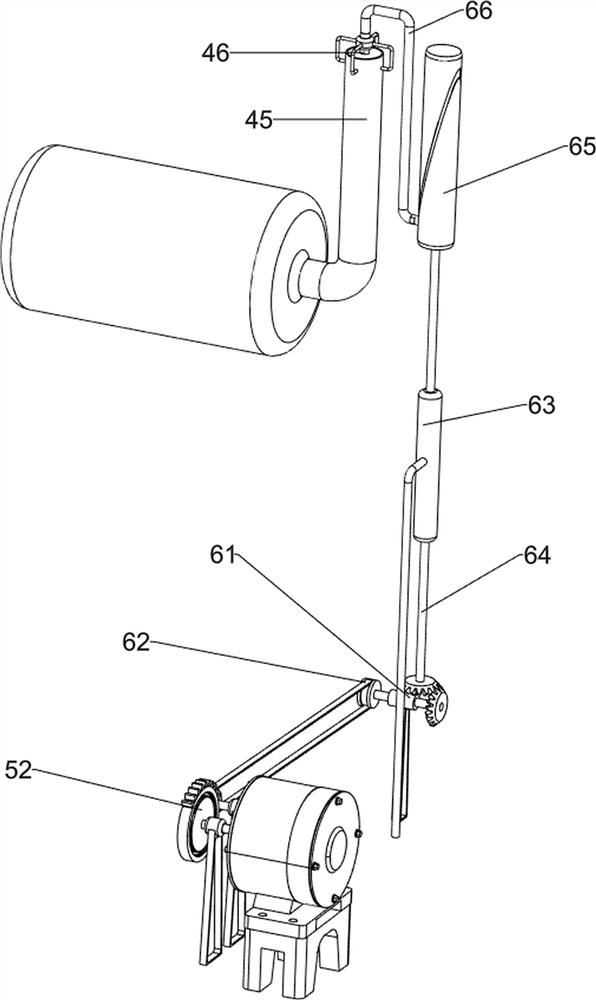
[0068] On the basis of Example 1, such as figure 2 , image 3 , Figure 4 , Figure 6 and Figure 7As shown, the pressurized spraying mechanism 4 includes a support frame 41, an alcohol bucket 42, a spray nozzle 43, a ball valve 44, a booster pipe 45 and a booster piston assembly 46, and the bottom plate 1 is provided with two support frames 41 in the upper middle, and the left and right sides The upper side of the support frame 41 is provided with an alcohol barrel 42, the bottom of the alcohol barrel 42 is provided with a nozzle 43, the upper part of the nozzle 43 is rotatably provided with a ball valve 44, the right side of the alcohol barrel 42 is provided with a booster tube 45, and the upper side of the booster tube 45 is a sliding type A booster piston assembly 46 is provided.
[0069] First, pour the alcohol into the alcohol barrel 42. When the alcohol needs to be sprayed, manually move the pressurized piston assembly 46 up and down. After increasing the pressure ...
Embodiment 3
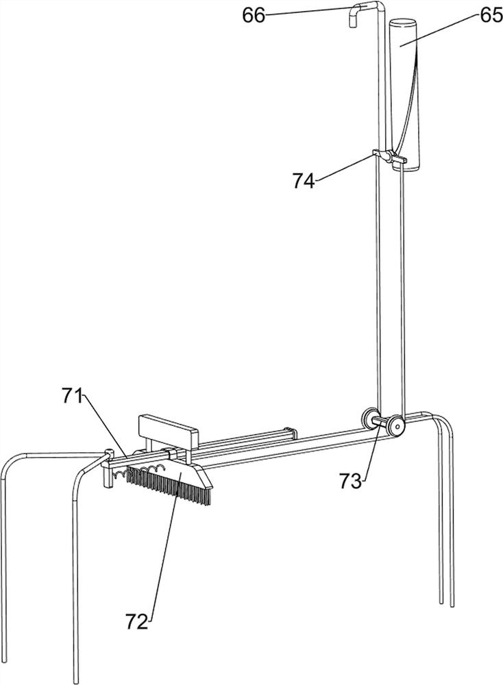
[0073] On the basis of Example 2, such as figure 1 , Figure 4 , Figure 5 , Figure 6 and Figure 7 As shown, a telescopic mechanism 6 is also included, and the upper right side of the bottom plate 1 is provided with a telescopic mechanism 6. The telescopic mechanism 6 cooperates with the pressurized spraying mechanism 4 and the transmission clamping mechanism 5. The second transmission assembly 62, the third rotary sleeve 63, the direction-changing rotary assembly 64, the tank barrel 65 and the guide connecting rod 66, the upper right side of the bottom plate 1 is provided with two second rotary sleeves 61, and the upper parts of the two second rotary sleeves 61 rotate The second transmission assembly 62 is provided with the second transmission assembly 62, and the second transmission assembly 62 cooperates with the missing gear 52. The third rotary sleeve 63 is provided at the middle of the upper right side of the bottom plate 1, and the rear rotation of the upper part o...
PUM
 Abstract
Description
Claims
Application Information
 - R&D
- Intellectual Property
- Life Sciences
- Materials
- Tech Scout
- Unparalleled Data Quality
- Higher Quality Content
- 60% Fewer Hallucinations
Browse by: Latest US Patents, China's latest patents, Technical Efficacy Thesaurus, Application Domain, Technology Topic, Popular Technical Reports.
© 2025 PatSnap. All rights reserved.Legal|Privacy policy|Modern Slavery Act Transparency Statement|Sitemap|About US| Contact US: help@patsnap.com


