Eureka AIR delivers breakthrough ideas for toughest innovation challenges, trusted by R&D personnel around the world.

Forming jig for chip frame pin

A jig and frame technology, which is applied in the field of forming jigs for chip frame pins, and can solve problems such as metal tin peeling

Pending Publication Date: 2021-04-23
星科金朋半导体(江阴)有限公司
View PDF0 Cites 0 Cited by
  • Summary
  • Abstract
  • Description
  • Claims
  • Application Information

AI Technical Summary

Problems solved by technology

However, in the process of processing, the metal tin peels off due to excessive impact of the forming jig or friction with the frame pin 22 or defects in the shape of the forming jig itself.

Method used


Image

  • Forming jig for chip frame pin
  • Forming jig for chip frame pin
  • Forming jig for chip frame pin

Examples


Embodiment

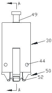
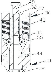
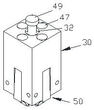
[0077] A molding tool for chip frame pins of the present invention, such as figure 1Shown is a schematic diagram of the structure of its forming fixture. The forming jig includes a stamping body part 30 , a thin pin 44 , a main shaft 60 , a bolt 49 , a forming support 50 and a forming base 10 , and the forming base 10 is arranged directly below the main shaft 60 . Such as Figure 2 to Figure 5 as shown, figure 2 for figure 1 The schematic diagram of the A-A section structure; image 3 and Figure 4 for figure 1 The schematic diagram of the three-dimensional structure; Figure 5 for figure 1 exploded diagram.

[0078] Such as Figure 6 As shown, it is a three-dimensional structural schematic diagram of the stamped main body part 30. The stamped main body part 30 is table-shaped, including a desktop and a pillar 31, and the pillar 31 is vertical to the desktop. Generally, the pillar 31 of the stamped main body part 30 is provided with Four are respectively arranged at...


PUM

PropertyMeasurementUnit
surface roughnessaaaaaaaaaa

Abstract

The invention relates to a forming jig for a chip frame pin, and belongs to the technical field of semiconductor jigs. A main through hole is formed in the center of a table top of a stamping main body part (30) of the forming jig, the main through hole is longitudinally matched with a main shaft (60) in shape in a stepped mode, the main shaft (60) is inserted into the main through hole of the stamping main body part (30) from front to back, a bolt (49) penetrates into the main through hole of the stamping main body part (30) from the top, the main shaft (60) is in threaded connection with the bolt (49) in the stamping main body part (30), forming supporting legs (50) are vertically embedded between adjacent supporting columns (31) of the stamping main body part (30), and forming rolling wheels (52) are arranged at the front ends of the forming supporting columns (50). According to the forming jig for the chip frame pin, the condition of metal tin peeling can be reduced, and the product qualification rate is improved.

Description

technical field [0001] The invention relates to a molding jig for chip frame pins, belonging to the technical field of semiconductor jigs. Background technique [0002] In large-scale or ultra-large-scale integrated circuits, square flat package products are often used, and the number of pins is generally more than 100. Since the pins of the CPU chip of the square flat package structure (QFP) are very small and the pins are very thin, metal tin is often used to protect the copper pins from oxidation. However, during the processing, the metal tin peels off due to excessive impact force of the forming jig or friction with the frame pin 22 or defects in the shape of the forming jig itself. Contents of the invention [0003] The purpose of the present invention is to overcome the deficiencies in the prior art, and provide a molding jig for chip frame pins, so as to improve the qualified rate of products. [0004] The present invention is achieved like this: [0005] The inv...

Claims


Application Information

Patent Timeline
Patent Type & Authority Applications(China)
IPC IPC(8): B21F1/02B21F1/00
CPCB21F1/004B21F1/02
Inventor 郑煜程金健李越韩帅李斌沈国强
Owner 星科金朋半导体(江阴)有限公司
Why Eureka
Eureka Blog
Learn More