
Milling detection equipment

A detection equipment, milling technology, applied in milling machine equipment, milling machine equipment details, measuring/indicating equipment, etc., can solve problems such as inability to guarantee product processing quality, low processing efficiency, and low pass rate

Pending Publication Date: 2021-04-23
WARNER SHENGLONG NINGBO CO LTD
View PDF0 Cites 4 Cited by
  • Summary
  • Abstract
  • Description
  • Claims
  • Application Information

AI Technical Summary

Problems solved by technology

This means that after the height difference detection is performed on the detection workbench, it needs to be transported to the lathe for operation. With this process, there is no continuity in the product detection and processing procedures, so that the processing quality and pass rate of the product cannot be guaranteed. Low, and the processing time is long after the product is moved, and the processing efficiency is low

Method used


Image

  • Milling detection equipment
  • Milling detection equipment
  • Milling detection equipment

Examples


Embodiment Construction

[0034] The following will clearly and completely describe the technical solutions in the embodiments of the present invention with reference to the accompanying drawings in the embodiments of the present invention. Obviously, the described embodiments are only part of the embodiments of the present invention, not all of them. Based on the embodiments of the present invention, all other embodiments obtained by persons of ordinary skill in the art without creative efforts fall within the protection scope of the present invention.

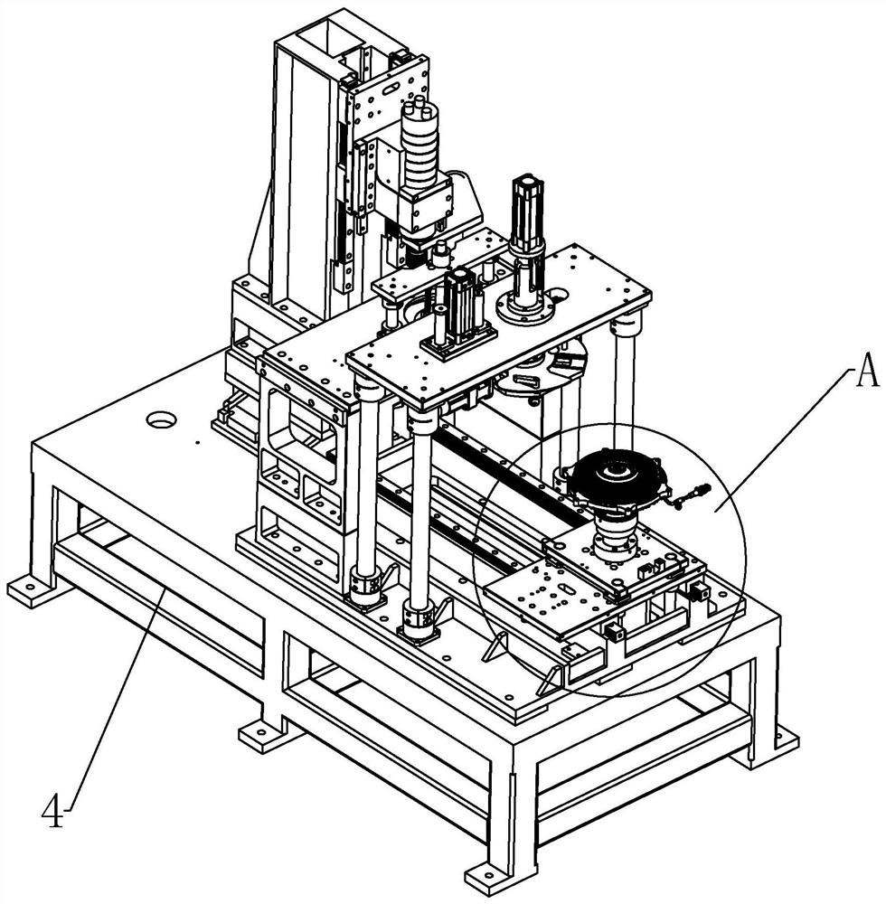
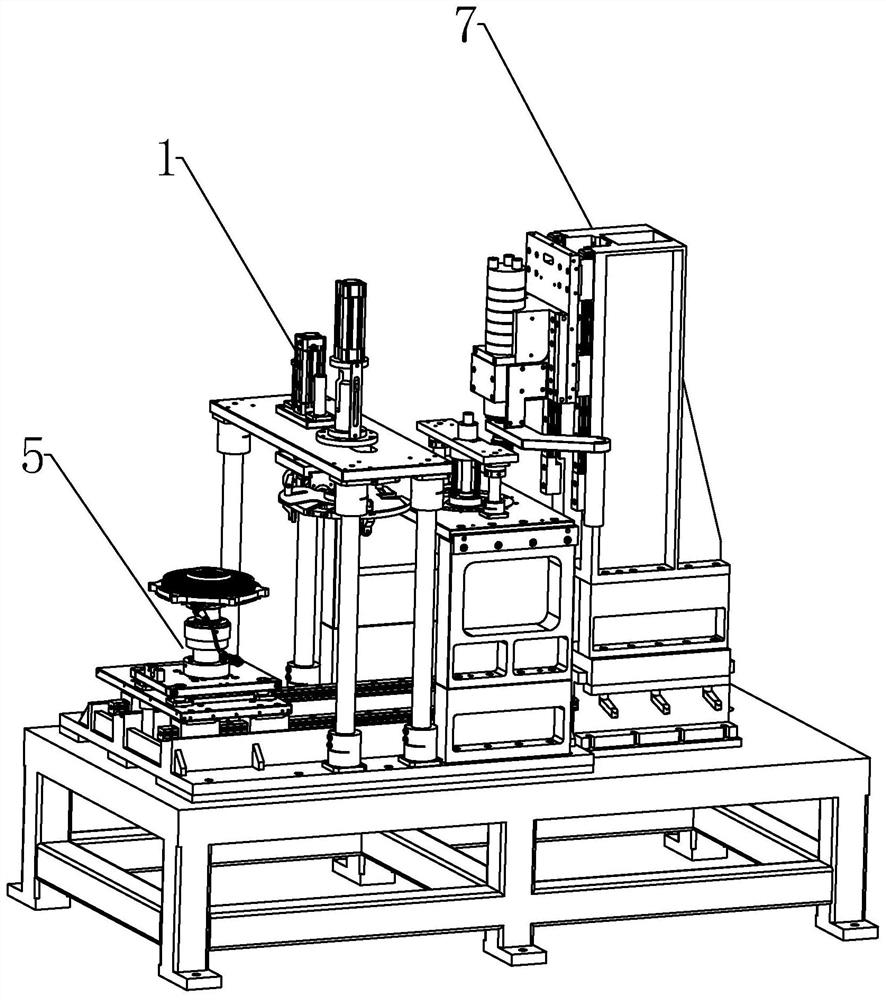
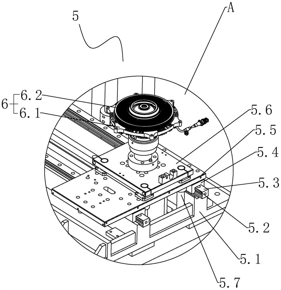
[0035] Such as figure 1 with figure 2 As shown, a milling inspection device is shown, which integrates the inspection and milling procedures on one machine to facilitate the processing of active board 6.2 products. The equipment includes a frame 4, on which a feeding mechanism 5, a detection mechanism 1, a processing mechanism 7 and a controller are arranged, wherein the feeding mechanism 5 is used to place and fix the product 6 to be detected and m...


PUM


Abstract

The invention discloses milling detection equipment which comprises a rack. A feeding mechanism, a detection mechanism, a machining mechanism and a controller are arranged on the rack. The detection mechanism is used for detecting the height difference between a shell and a driving plate of a product; the machining mechanism is used for milling the driving plate of product; the feeding mechanism is used for fixing the product and conveying the product to the detection mechanism and the machining mechanism in sequence for detection and machining; and the controller is electrically connected with the feeding mechanism, the detection mechanism and the machining mechanism. According to the equipment, the detection procedure and the milling procedure are integrated on one machine, the continuity between the two procedures is improved, and the machining quality and the machining efficiency of the product can be improved by adopting the equipment.

Description

technical field [0001] The invention relates to the technical field of processing equipment, in particular to a milling detection equipment. Background technique [0002] With the development of the national economy, the requirements for energy saving and environmental protection of automobiles are getting higher and higher. Most of the working time of automobiles does not need fan cooling, so the automatic fan clutch technology of automobiles is a key technology for automobile energy saving. As the core component of the automobile engine cooling system, the electronically controlled silicon oil fan clutch has an important impact on the performance of the engine. Among them, the assembly height difference between the housing and the active plate in the electronically controlled silicon oil fan clutch will affect its performance. [0003] In the prior art, the shell and the active plate are press-fitted first, and the height difference between the active plate and the shell ...

Claims


Application Information

Patent Timeline
IPC IPC(8): B23Q7/00B23Q11/00B23Q3/06B23C3/00B23Q17/20B23P19/02
CPCB23Q7/00B23Q11/0046B23Q3/06B23C3/00B23Q17/20B23P19/02
Inventor 蒋联忠丁小阳王林顾建坤
Owner WARNER SHENGLONG NINGBO CO LTD
Learn More