
A mechanical processing equipment for the production of auto parts

A technology for auto parts and mechanical processing, applied in metal processing equipment, grinding machine parts, grinding/polishing equipment, etc., can solve the problems of poor adjustment accuracy, low efficiency, slow speed, etc., and achieve high safety , high efficiency, fast effect

Active Publication Date: 2021-12-03
江西华盛精诚智能装备有限公司
View PDF4 Cites 1 Cited by
  • Summary
  • Abstract
  • Description
  • Claims
  • Application Information

AI Technical Summary

Problems solved by technology

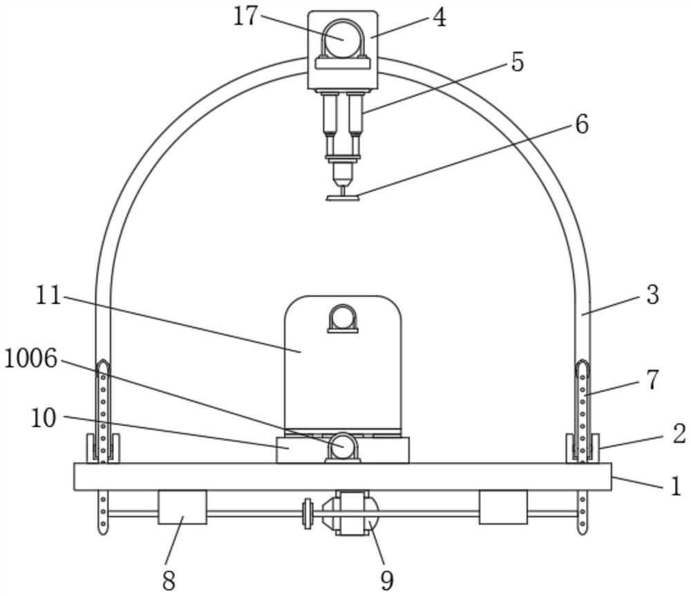
[0005] In view of the above situation, in order to overcome the defects of the prior art, the present invention provides a kind of mechanical processing equipment for producing auto parts, which effectively solves the slow speed of manual adjustment required for the angle adjustment of the grinding device in the above background technology, The problem of low efficiency and poor adjustment accuracy

Method used


Image

  • A mechanical processing equipment for the production of auto parts
  • A mechanical processing equipment for the production of auto parts
  • A mechanical processing equipment for the production of auto parts

Examples


Embodiment 1

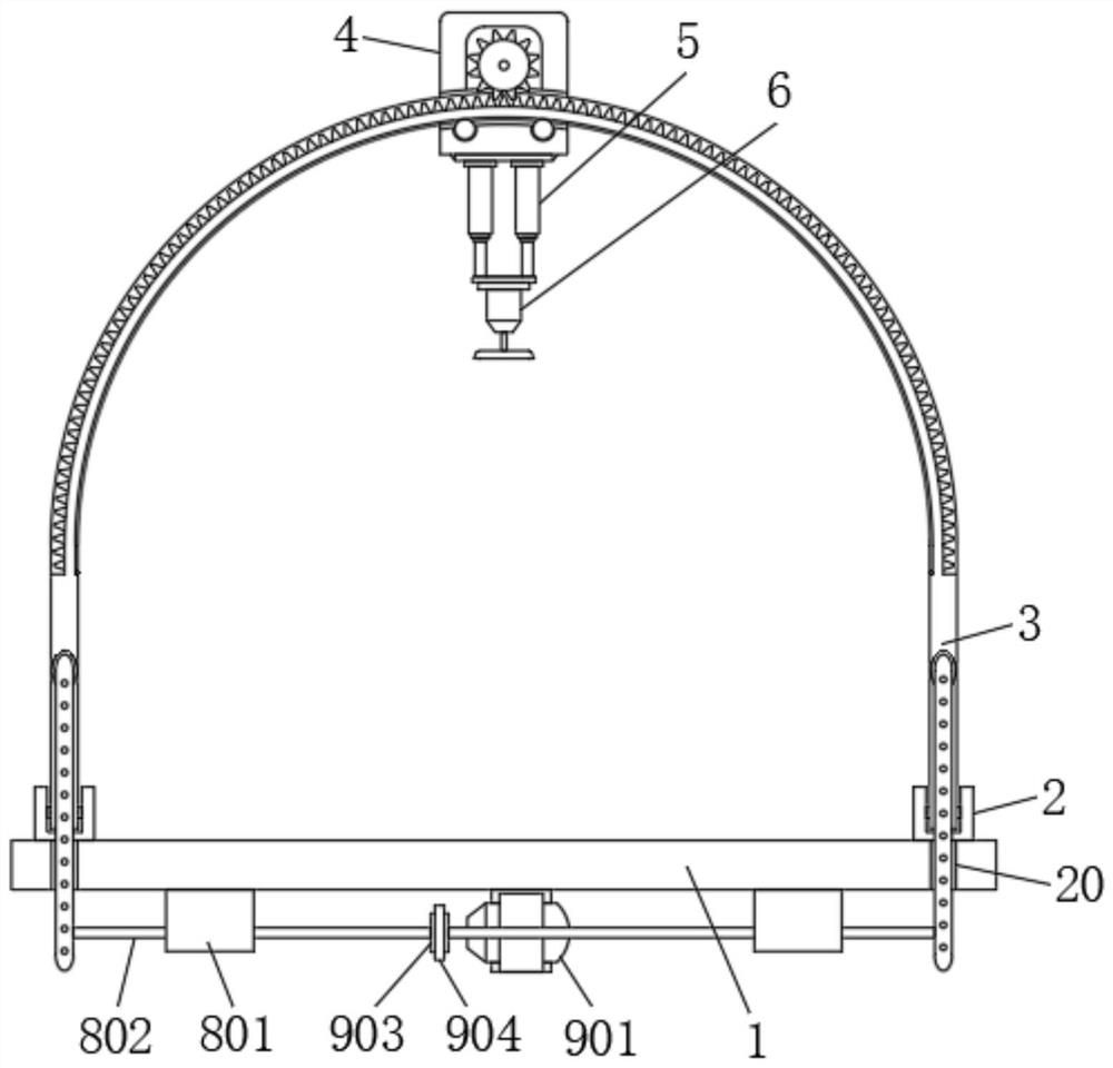
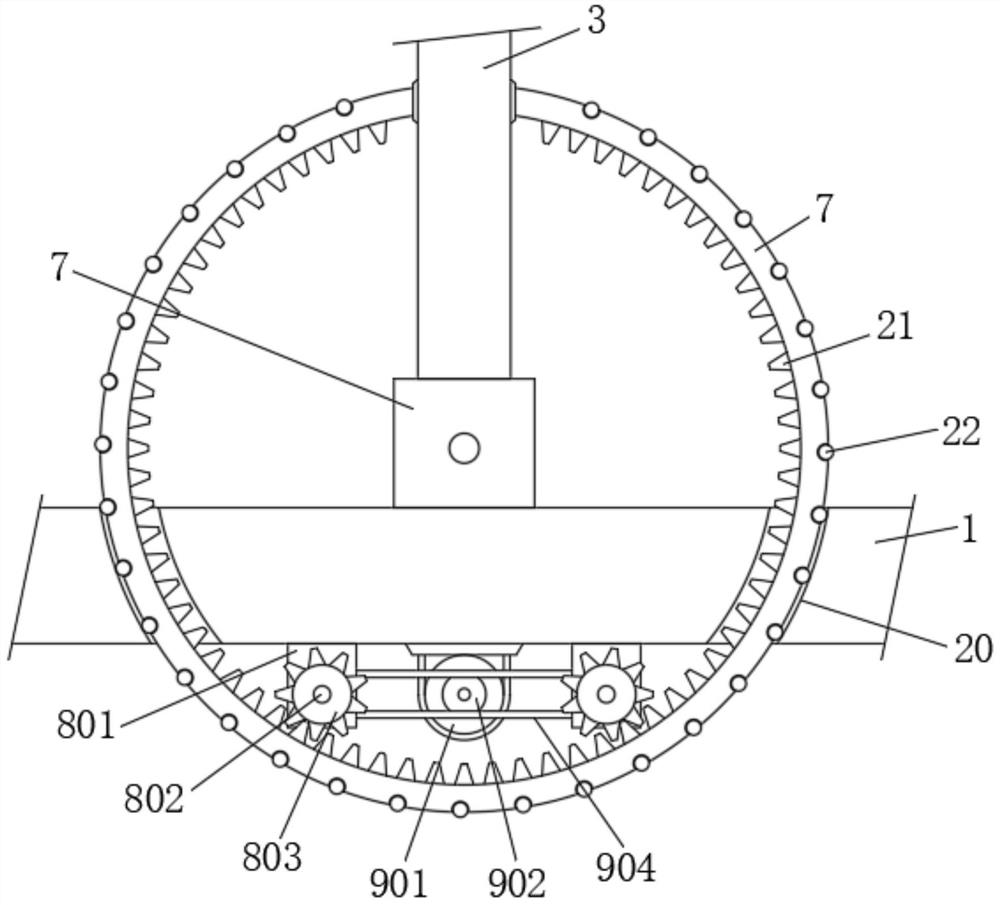
[0030] First embodiment, the Figure 1 to 6Are given, the present invention comprises a base 1, both ends of the top side of the chassis 1 are connected to base 2 is fixedly mounted, two connecting base 2 rotatably mounted between the arcuate inner rotating lever 3, is provided by connecting the base 2, rotating lever 3 so that the arc can be effectively installed and rotated, the arcuate bottom central rotation shaft 3 is mounted, the bottom of the moving block 4 of the moving block 4 are mounted two hydraulic telescopic cylinders 5, two hydraulic telescopic cylinder 5 of between the grinding machine 6 is mounted, the arcuated ends between the rod 3 and the base ends are attached to a fixed circle 7, the bottom of the base 1 is attached to both ends of the two drive rods 8, two drive rod 8 are respectively connected to two gear 7 fixed circle, and the bottom of the base 1 is positioned between the transmission lever 8 is mounted has two adjustable power end 9, the central base is ...

Embodiment 2

[0032] According to the second embodiment, on the basis of the first embodiment, the Figure 4 Given arc of rotation of the lever 3 intrados defines two ball grooves 18, on both sides of the central arcuate through slot 14 are mounted on the first two balls 19, 19 is fixed to the movable first ball in the ball detent grooves interior 18, so that the movement of the moving block 4 can be stabilized.

Embodiment 3

[0033] The third embodiment, on the basis of the first embodiment, the image 3 Given, both sides of the base 1 defines two arcuate grooves 20 on both ends 7 of the fixed circle rotating lever 3 connected by two stationary arcuate slot 20 and through the arcuate, fixed inside two circles 7 equalization is mounted from a second fixing teeth 21, two outer circles uniformly fixed distance 7 is mounted a second ball 22, by providing the second ball 22, with the mounting circle 7 can be rotated easily adjusted.


PUM


Abstract

The invention relates to the technical field of mechanical processing equipment for auto parts, and discloses a mechanical processing equipment for producing auto parts, which solves the problem that the angle adjustment of the grinding device requires manual adjustment, which requires slow speed, low efficiency, and adjustment accuracy. Poor problem, which includes the base, the two ends of the top side of the base are fixedly installed with connecting seats, the inner sides of the two connecting seats are rotated and installed with an arc-shaped rotating rod, and the middle part of the arc-shaped rotating rod is installed with a moving block , two hydraulic telescopic cylinders are installed at the bottom of the moving block, a grinder is installed between the bottoms of the two hydraulic telescopic cylinders, and fixed circles are installed between the two ends of the arc-shaped rotating rod and the two ends of the base; The parts machining, polishing and grinding equipment can automatically adjust the angle, and the angle adjustment speed is fast, the efficiency is high, and the adjustment accuracy is high. At the same time, the adjustment process is stable and reliable, and the safety is high, which can meet the processing and use requirements of auto parts.

Description

Technical field [0001] The present invention belongs to the automotive technical field of machining equipment parts, in particular for the production of automotive components machining equipment. Background technique [0002] Auto parts constitute the whole of auto parts processing units and services in the auto parts processing products; and automotive components required for surface polishing processing in the production process, so as to ensure the aesthetics of auto parts processing, and parts convenience in subsequent processing and use. [0003] Patent Application Publication No. CN211249540U, discloses a system for facilitating auto parts with adjustable angle grinding apparatus, the grinding means of the following structures: the tooling table; fixed plate; loading plate; pegboard; clamping bolt; fixed block; chute; carriage; transposition; contact lever; lug plate; a first threaded rod; flap; a second threaded rod; slide shaft; a first motor; arcuate carriage; sleeve; fi...

Claims


Application Information

Patent Timeline
Patent Type & Authority Patents(China)
IPC IPC(8): B24B27/00B24B41/06B24B41/02B24B47/22B24B47/08
CPCB24B27/0046B24B41/02B24B41/06B24B47/08B24B47/22
Inventor 左二俚
Owner 江西华盛精诚智能装备有限公司
Learn More