Pipe unloading and translation mechanism

A technology of translation mechanism and material pushing mechanism, which is applied in the direction of conveyor, conveyor objects, transportation and packaging, etc. It can solve problems such as difficult pipes, poor cutting quality, and high work intensity of workers, so as to achieve efficient and smooth rolling and unloading, and improve Efficiency and quality, the effect of reasonable structural design

Inactive Publication Date: 2018-10-26
桐乡市川泰纺织科技有限公司
View PDF0 Cites 10 Cited by
  • Summary
  • Abstract
  • Description
  • Claims
  • Application Information

AI Technical Summary

Problems solved by technology

During the production and processing of pipes, it is necessary to cut the pipes with longer dimensions according to the needs of later welding processing, so that the pipes cut into segmental structures can meet the needs of various uses. During the cutting process, one method is to place the pipe horizontally and stably, and then move the cutting mechanism horizontally along the direction of the pipe placement, so that the pipe can be cut into sections as needed, and the length of the pipe cut is determined by the translation of the cutting mechanism. The distance is determined by this method. This method is mainly aimed at the section processing of pipes with large dimensions and heavy weight. Another method is to fix the cutting mechanism and move the pipe horizontally along the conduit mechanism. According to the required The length of the pipe will translate the pipe level smoothly and accurately, and then use the cutting mechanism to cut the pipe after moving the pipe to the desired position. This method is mainly aimed at pipes with small sizes and easy translation. The existing pipe translation mechanism In the process of use, it is necessary to manually lift the long pipe horizontally to the upper side of the translation mechanism. The work intensity of the workers is relatively high, and in the process of translation of the pipe, the existing translation mechanism is difficult to realize according to the needs of actual use. The level of the pipe is accurately translated, resulting in low cutting efficiency and poor cutting quality of the pipe, which cannot meet the needs of processing and use

Method used


Image

  • Pipe unloading and translation mechanism
  • Pipe unloading and translation mechanism
  • Pipe unloading and translation mechanism

Examples


Embodiment Construction

[0018] In order to further describe the present invention, a specific implementation of a pipe blanking translation mechanism will be further described below in conjunction with the accompanying drawings. The following examples are explanations of the present invention and the present invention is not limited to the following examples.

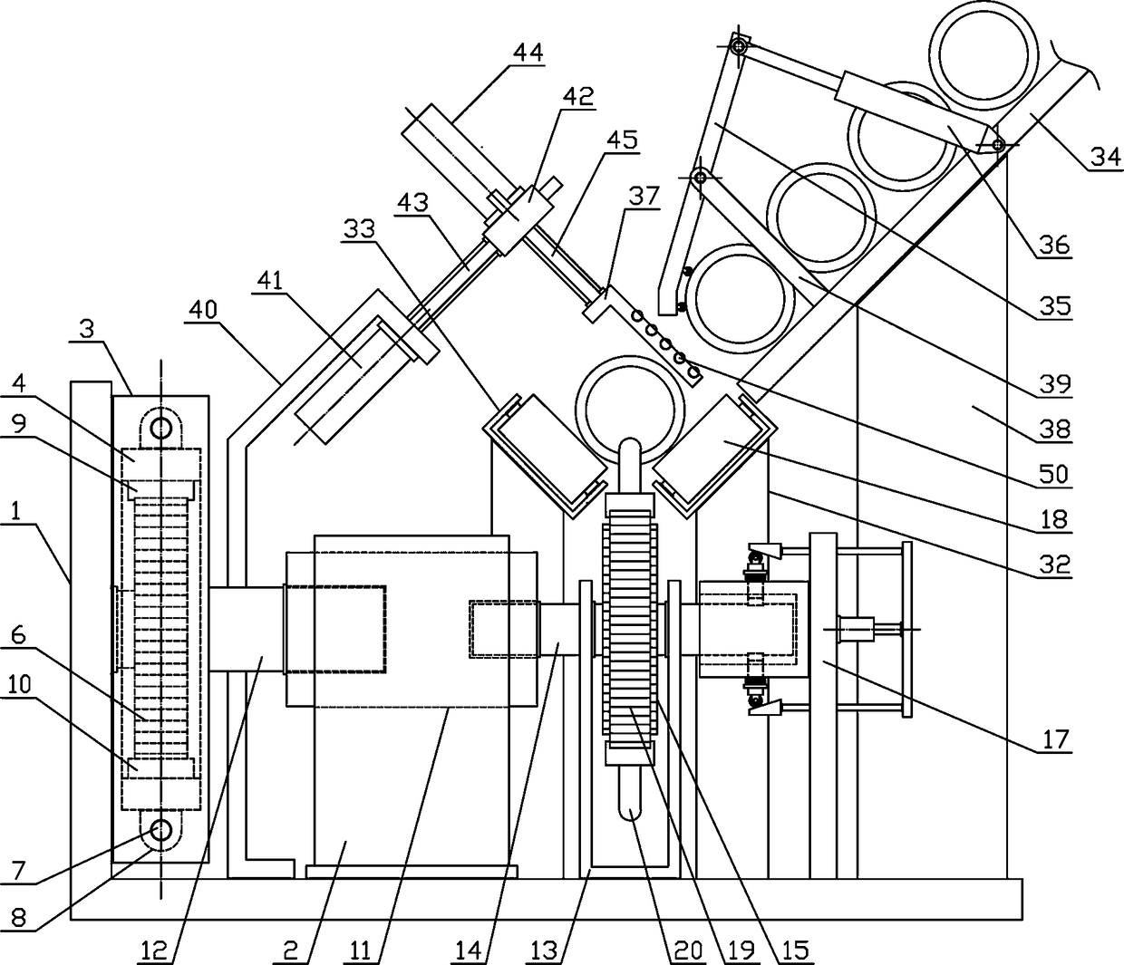
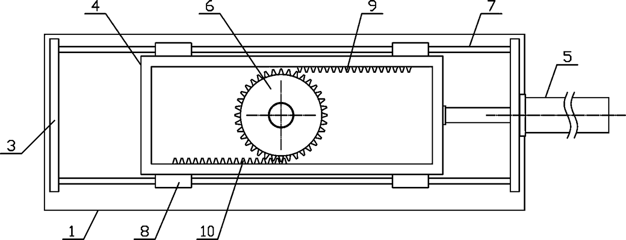
[0019] Such as figure 1 As shown, a pipe material blanking translation mechanism of the present invention includes a fixed base 1, a reciprocating drive mechanism, a connecting bracket 2, a pushing mechanism and a blanking mechanism. The material mechanism is vertically arranged on the middle part of the upper side of the fixed base 1, the connecting bracket 2 is vertically fixedly arranged between the reciprocating drive mechanism and the pushing mechanism, and the unloading mechanism is arranged on the upper side of the pushing mechanism. Such as figure 2 As shown, the reciprocating drive mechanism of the present invention includes a trans...


PUM


Abstract

The invention discloses a pipe unloading and translation mechanism, and belongs to the field of building material machining mechanical equipment. A reciprocating driving mechanism is vertically fixedon one side of the upper side of a fixed base; a connecting bracket is vertically fixed between the reciprocating driving mechanism and a pushing mechanism; an unloading mechanism is arranged on the upper side of the pushing mechanism; the connecting bracket is horizontally and rotationally connected with an electromagnetic clutch; one end of a one-way clutch on one side of a rotating gear is horizontally arranged in the electromagnetic clutch; a pushing rotating shaft above a pushing bracket is horizontally arranged in the electromagnetic clutch; a damping mechanism is arranged at one end ofthe pushing rotating shaft; pipe pushing support rods are symmetrically arranged on the outer side of a pushing chain; and an unloading mechanism comprises a pipe guide inclined plate, a pipe stop rotating rod, a lower pipe cylinder and a lower pipe baffle plate. The pipe unloading and translation mechanism is reasonable in structural design, can gradually and stably unload pipes, and can flatly shift the pipes as needed efficiently and accurately to meet the machining and use demands.

Description

technical field [0001] The invention belongs to the field of building material processing machinery and equipment, and in particular relates to a pipe blanking translation mechanism, which is mainly used in the field of pipe translation processing. Background technique [0002] Pipe is the material used to make pipe fittings. Different pipes use different pipes. The quality of pipes directly determines the quality of pipes. Pipes are necessary materials for construction projects. Commonly used are water supply pipes, drain pipes, gas pipes, and heating pipes. Pipes, wire conduits and rainwater pipes, etc., with the development of science and technology, the pipes used in home decoration have also experienced from ordinary cast iron pipes, cement pipes, reinforced concrete pipes and asbestos cement pipes to ductile iron pipes, galvanized steel pipes, plastic pipes and The development process of aluminum-plastic composite pipe. According to the usage of the pipe, there are ma...

Claims


Application Information

Patent Timeline
Patent Type & Authority Applications(China)
IPC IPC(8): B65G17/40B65G47/88
CPCB65G17/40B65G47/88
Inventor 朱晓强
Owner 桐乡市川泰纺织科技有限公司
Why Eureka
Try Eureka