Continuous reciprocating clamping-transferring mechanism

A technology of transfer mechanism and material transfer mechanism, which is applied in the field of continuous transfer and feeding of textile materials and continuous reciprocating material transfer mechanism, can solve the problems of low material transfer efficiency, narrow application range, large energy consumption, etc., and achieve efficient transfer and loading. material, improve the degree of automation, and the effect of reasonable structure design

Inactive Publication Date: 2019-02-01
桐乡市红旗塑料包装袋厂
View PDF0 Cites 9 Cited by
  • Summary
  • Abstract
  • Description
  • Claims
  • Application Information

AI Technical Summary

Problems solved by technology

When producing and processing woolen materials using the above-mentioned various processes, it is necessary to first load the raw material washed wool for loosening and dust removal, and then store the wool. After the raw material washed wool is processed through the above process steps in turn In order to continue to carry out subsequent processes such as combing and slivering, the existing woolen materials are in the process of opening the first process, and the woolen materials are mainly loaded manually during the feeding process, and workers need continuous The woolen material is transported to the opener by means of wool spinning forks and other tools, the labor intensity of the workers is relatively high, and it is difficult to achieve continuous and uniform feeding of the woolen material during the feeding process of the woolen material, which makes it difficult for the woolen opener Smooth and efficient processing of woolen materials evenly and orderly, reducing the processing quality and processing efficiency of woolen materials
In the feeding process of existing woolen materials, the driving mechanism is mainly used to drive the transfer platform to reciprocate for translation, so as to realize continuous translational feeding of woolen materials. The reciprocating mechanism of the transfer platform generally uses a motor to drive a screw rod and a hydraulic cylinder to drive a piston rod. , The motor-driven screw rod is threadedly connected with the transfer platform by using the screw rod. The motor drives the screw rod forward and reverse through forward and reverse, so that the transfer platform can be reciprocated for transportation. The hydraulic cylinder drives the piston rod to fix the transfer platform with the piston rod. The hydraulic cylinder drives the piston rod reciprocally so that the piston rod can reciprocate and stretch, so that the transfer platform can be reciprocated for transportation. The above-mentioned driving method of the transfer platform causes a large loss of equipment, and it is often necessary to replace the worn parts. During the driving process of the platform, the energy consumption is also relatively large. During the reciprocating transmission process of the existing transfer platform, it is difficult to transfer the transfer platform evenly and smoothly according to the needs of material transmission, and the material transmission efficiency is low. It is suitable for The range is narrow, which reduces the efficiency and quality of material transportation and processing, and it is difficult to meet the needs of processing and use

Method used


Image

  • Continuous reciprocating clamping-transferring mechanism
  • Continuous reciprocating clamping-transferring mechanism
  • Continuous reciprocating clamping-transferring mechanism

Examples


Embodiment Construction

[0018] In order to further describe the present invention, a specific implementation of a continuous reciprocating card material transfer mechanism will be further described below in conjunction with the accompanying drawings. The following examples are explanations of the present invention and the present invention is not limited to the following examples.

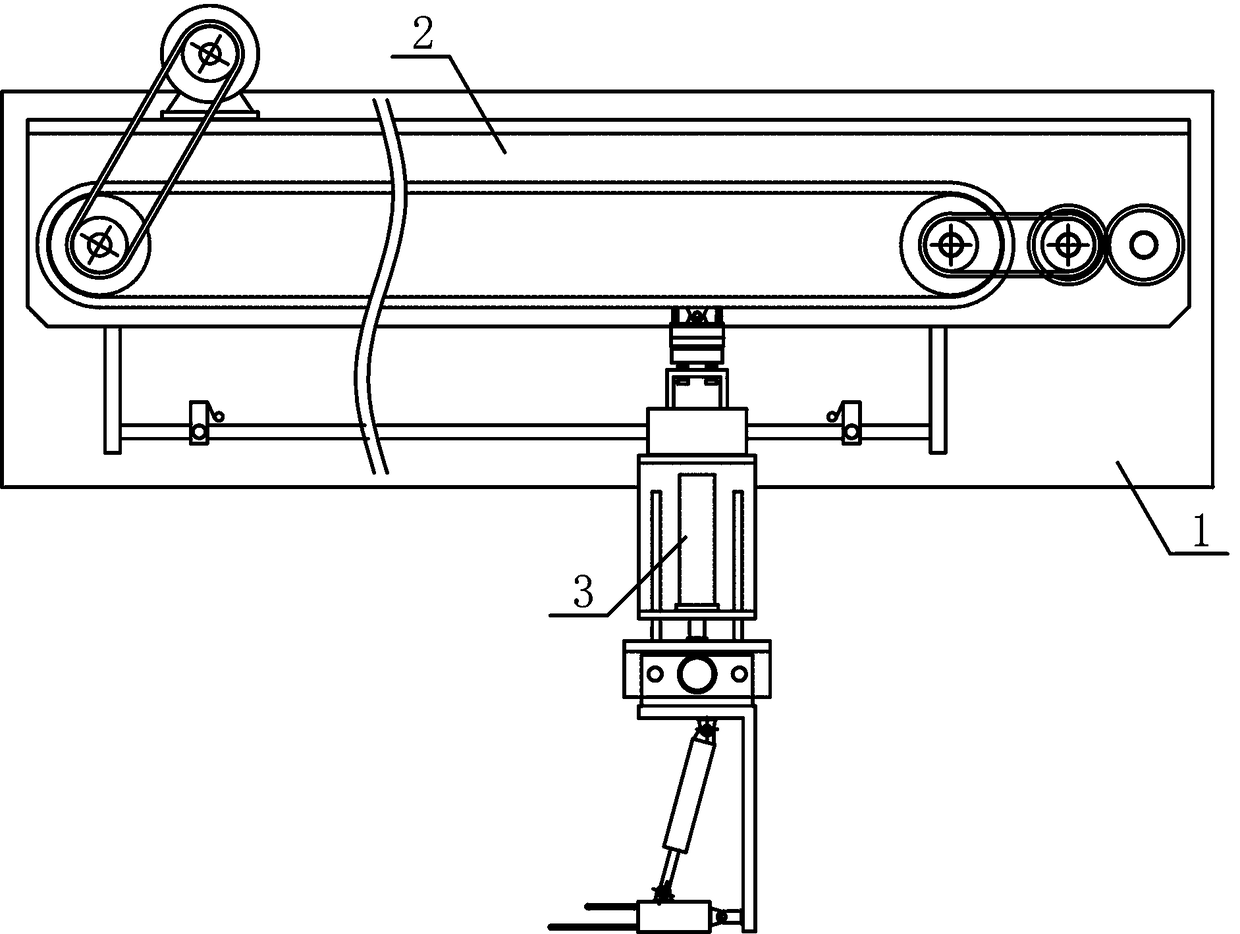
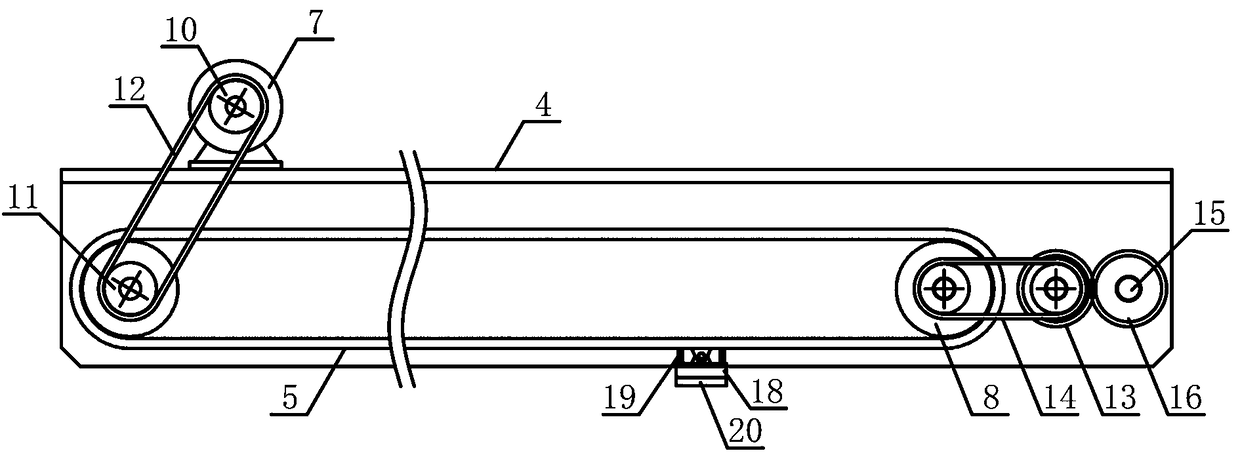
[0019] Such as figure 1 As shown, a continuous reciprocating material transfer mechanism of the present invention includes a transmission bracket 1, a drive mechanism 2 and a material transfer mechanism 3, the drive mechanism 2 is horizontally fixed on the upper side of the transmission bracket 1, and the material transfer mechanism 3 is vertically arranged on the drive body 2 underside, such as figure 2 As shown, the driving mechanism 2 of the present invention comprises a belt guide bracket 4, a main material transfer belt 5, an auxiliary material transfer belt 6 and a material transfer motor 7, the belt guide bracket ...


PUM


Abstract

The invention discloses a continuous reciprocating clamping-transferring mechanism and belongs to the field of mechanical equipment for textile material transportation. The continuous reciprocating clamping-transferring mechanism is characterized in that a transferring mechanism is vertically arranged on the lower side of a driving mechanism; a main transferring belt and an auxiliary transferringbelt are horizontally arranged on two sides of the lower part of a guiding belt bracket; the rotating transportation speed of a front transferring belt and that of a rear transferring belt are the same; a transferring electromagnet is horizontally arranged on the upper side of an adsorption base and the adsorption base is arranged on the upper side of a translation guiding plate; the output end ofa lifting air cylinder on an air cylinder bracket is fixedly connected with the middle of the upper side of a translation bracket; a transferring guiding plate is slidably arranged on transferring guiding rods in the horizontal direction; a clamping connecting plate is horizontally arranged on one side of the lower part of a transferring connecting plate; and a rotating air cylinder is arranged between the upper side of the clamping connecting plate and the transferring connecting plate. The continuous reciprocating clamping-transferring mechanism disclosed by the invention is reasonable in structural design; the translation guiding plate can be smoothly and accurately driven to perform translation motion in a continuous reciprocating manner; a textile material can be efficiently transferred and fed; the textile material feeding automation degree can be improved; and the processing and using requirements can be met.

Description

technical field [0001] The invention belongs to the field of textile material transport machinery and equipment, and in particular relates to a continuous reciprocating card material transfer mechanism, which is mainly used for continuous transfer and loading of textile materials. Background technique [0002] Wool spinning is a spinning process that processes wool fibers into yarns. Wool spinning fibers are mainly wool, and also include special animal hairs such as cashmere, rabbit hair, mohair, yak hair, etc. The wool spinning process can also be used for wool-type chemical fiber pure spinning, Blended and blended with other natural fibers. Wool fabrics, knitted fabrics, blankets, etc. made of pure and blended wool yarns have the characteristics of warmth retention, moisture absorption, elasticity and wear resistance. Clothes made of wool fabrics feel soft, plump and scratchy. It can be used to weave industrial materials, stationery and carpets. The wool spinning system ...

Claims


Application Information

Patent Timeline
Patent Type & Authority Applications(China)
IPC IPC(8): B65G25/04
CPCB65G25/04
Inventor 朱啸天
Owner 桐乡市红旗塑料包装袋厂
Why Eureka
Try Eureka