Polyurethane material shaping and cutting device for new energy automobile

A polyurethane material and new energy vehicle technology, applied in metal processing and other fields, can solve problems such as injuries, reduced work efficiency, time-consuming and labor-intensive problems

Active Publication Date: 2021-04-23
JIANGXI COLLEGE OF APPLIED TECH
View PDF16 Cites 3 Cited by
  • Summary
  • Abstract
  • Description
  • Claims
  • Application Information

AI Technical Summary

Problems solved by technology

[0005] In order to overcome the damage and omission of part of the material plate, which will cause time-consuming and labor-intensive situations, the cutting knife may also cause the operator to contact and cause injury, s

Method used


Image

  • Polyurethane material shaping and cutting device for new energy automobile
  • Polyurethane material shaping and cutting device for new energy automobile
  • Polyurethane material shaping and cutting device for new energy automobile

Examples


Embodiment 1

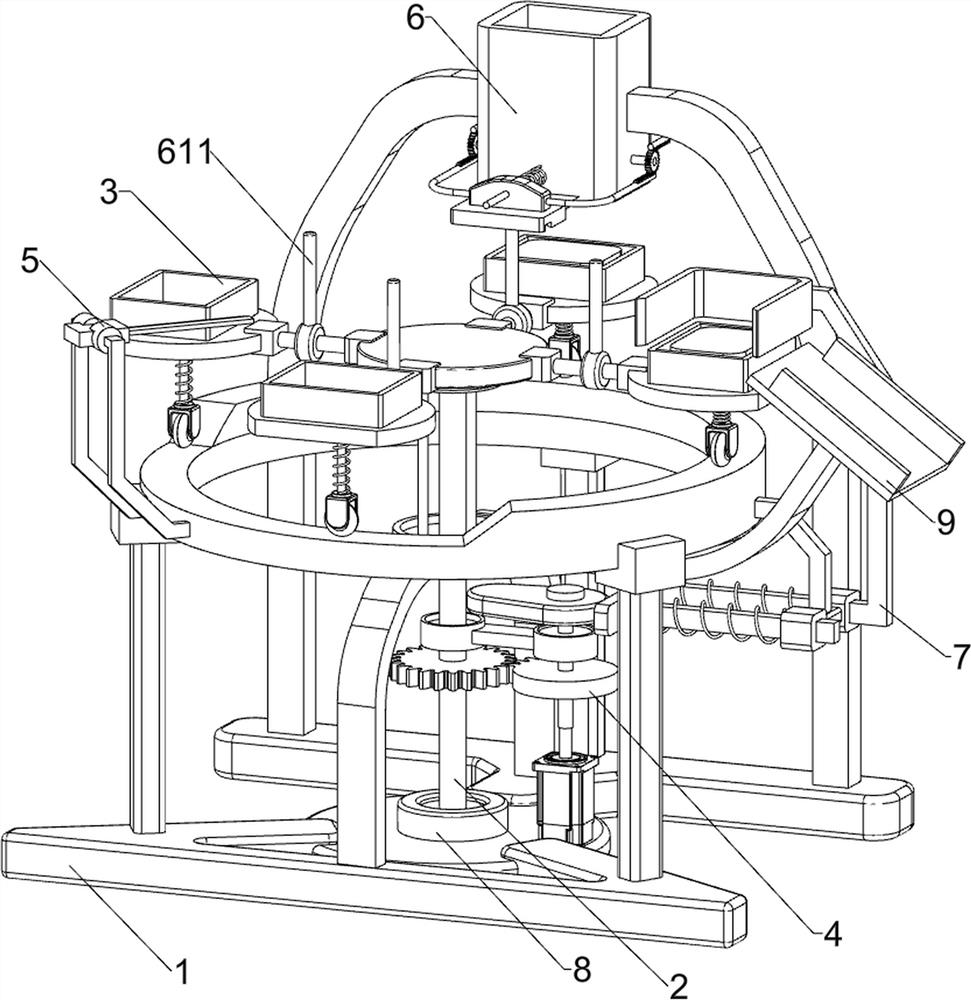
[0029] A polyurethane material shaping cutting device for new energy vehicles, such as figure 1 , figure 2 and image 3 As shown, it includes a base 1, a first support frame 2, a charging assembly 3, a transmission assembly 4 and a belt cutter 5. The middle part of the base 1 is rotatably provided with a first support frame 2, and the first support frame 2 and the base 1 A charging assembly 3 is arranged between them, a transmission assembly 4 is arranged on the right side of the middle part of the base 1, and a belt cutter 5 is arranged on the left front side of the upper part of the charging assembly 3.

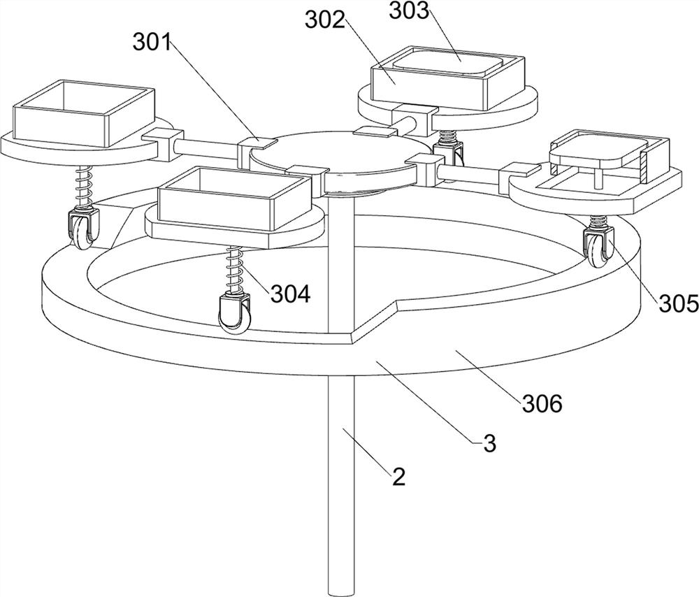
[0030] The charging assembly 3 includes a first connecting rod 301, a first baffle plate 302, a top plate 303, a first spring 304, a roller 305 and a contact frame 306, and the first supporting frame 2 top is provided with a first connecting rod 301 around the top. The outer sides of the connecting rods 301 are provided with a first baffle 302, the first baffle 302 is pr...

Embodiment 2

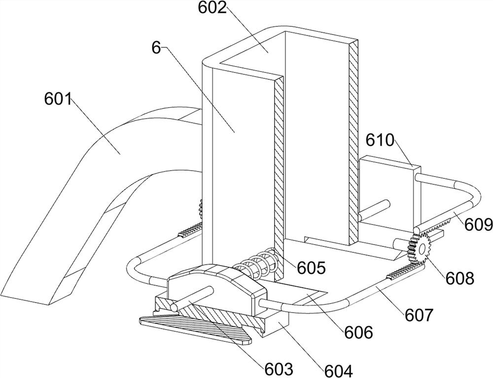
[0034] On the basis of Example 1, such as figure 1 , Figure 4 , Figure 5 , Image 6 and Figure 7 As shown, a blanking assembly 6 is also included, including a first bracket 601, a blanking cylinder 602, a first guide rod 603, a movable plate 604, a second spring 605, a second baffle plate 606, a first rack 607, The second gear 608, the second rack 609, the support plate 610 and the contact rod 611, the rear side of the base 1 is symmetrically provided with the first bracket 601, and the top of the first bracket 601 is provided with a blanking tube 602, and the blanking tube 602 The lower side is symmetrically provided with a first guide rod 603, and the front side of the first guide rod 603 is slidably provided with a movable plate 604, and a second spring 605 is connected between the movable plate 604 and the blanking cylinder 602, and the second spring 605 Set on the first guide rod 603 on the front side, the left and right sides of the movable plate 604 are provided ...


PUM


Abstract

The invention relates to a cutting device, and especially relates to a polyurethane material shaping and cutting device for a new energy automobile. The technical problem to be solved is to provide the polyurethane material shaping and cutting device for the new energy automobile, capable of realizing automatic cutting and automatic feeding, and convenient to operate. The technical scheme is as follows: the polyurethane material shaping and cutting device for the new energy automobile comprises a base, a first supporting frame, a charging assembly and a transmission assembly, wherein the first supporting frame is rotationally arranged at the middle part of the base; the charging assembly is arranged between the first supporting frame and the base; and the transmission assembly is arranged a one side of the middle part of the base. When people start a motor, an output shaft of the motor drives a transmission shaft to rotate, when a first gear rotates, the first supporting frame is driven to rotate, the first supporting frame drives a first connecting rod, a first baffle and a top plate to rotate around the first supporting frame, and meanwhile, the top plate drives a rolling wheel to move on a contact frame; and when a polyurethane material makes contact with a belt type cutter, the belt type cutter cuts the polyurethane material.

Description

technical field [0001] The invention relates to a cutting device, in particular to a polyurethane material shaping cutting device for new energy vehicles. Background technique [0002] Polyurethane material is a kind of polymer material and a new organic polymer material. It is known as the fifth largest plastic and is widely used in many fields of national economy because of its excellent performance. [0003] When people manufacture polyurethane materials, they generally cut the polyurethane material so that it can match the size of the new energy vehicle. At present, people fix the polyurethane material board manually, and then cut it with a hand-held cutting knife. This operation may It will cause damage and omission of part of the material plate, and it will cause time-consuming and labor-intensive situations. The cutting knife may also contact the operator and cause injury to him, so as to reduce work efficiency and increase labor costs. [0004] Therefore, it is part...

Claims


Application Information

Patent Timeline
IPC IPC(8): B26D1/46B26D7/06B26D7/18B26D7/00
CPCB26D1/46B26D7/06B26D7/1818B26D7/00B26D2007/0018
Inventor 谢剑和刘秋生姜云斐
Owner JIANGXI COLLEGE OF APPLIED TECH
Why Eureka
Try Eureka