
Flood control device

A technology of protective panels and mounting holes, applied in flood control panels, sealing devices, door/window protection devices, etc., can solve the problems of complicated installation and disassembly of flood control devices, reduced flood control work efficiency, and unsatisfactory flood control effects, and achieves difficult displacement. Or the effect of leakage, good flood control and stable structure

Active Publication Date: 2021-04-23
NANTONG INST OF TECH
View PDF6 Cites 3 Cited by
  • Summary
  • Abstract
  • Description
  • Claims
  • Application Information

AI Technical Summary

Problems solved by technology

[0004] The disadvantages of the above method are: because it is difficult to form a fixed support between the airbags or sealing strips and the door opening, especially in turbulent floods, these airbags or sealing strips distributed around the flood wall are easy to shift under the impact of water flow, Or the phenomenon of flood infiltration occurs at the edge, and the flood control effect is not ideal; and the existing flood control devices are generally complicated to install and disassemble, which reduces the efficiency of flood control work

Method used


Image

  • Flood control device
  • Flood control device
  • Flood control device

Examples


Embodiment Construction

[0033] In order to make the technical means, creative features, goals and effects achieved by the present invention easy to understand, the present invention will be further described below in conjunction with specific embodiments.

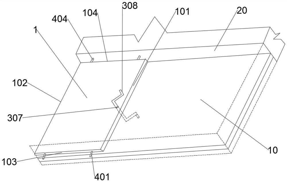
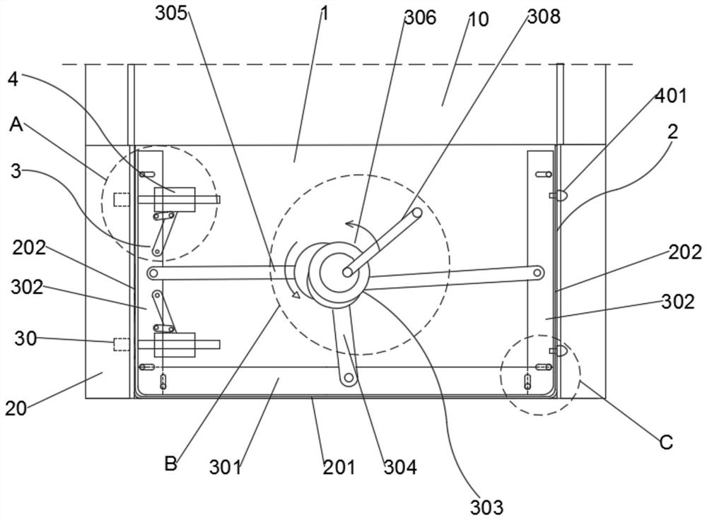
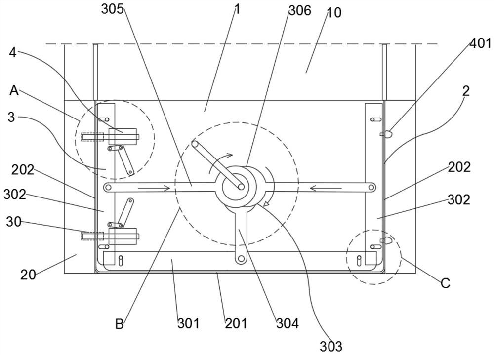
[0034] like Figure 1 to Figure 9 As shown, the present invention provides a flood control device, which can improve the flood control efficiency of the device. specific:

[0035] The flood protection device includes a protective plate 1 , a waterproof sealing component 2 , a side thrust component 3 and a positioning component 4 .

[0036] Wherein, the protective plate 1 is arranged in the middle of the door opening 10 that needs to be protected against floods, and includes an upper edge 101 , a lower edge 102 , a first side 103 and a second side 104 . Except for the inner wall 20 at the upper end of the doorway 10, the remaining inner walls 20 all need to be sealed and blocked by the flood prevention device of the present invention.

[0037] W...


PUM


Abstract

The invention discloses a flood control device. The flood control device comprises a protection plate, a waterproof sealing assembly, a side pushing assembly and a positioning assembly, wherein the protection plate is arranged in the middle of a door opening; the waterproof sealing assembly comprises a lower end sealing piece and two side edge sealing pieces which are arranged on the side edges of the protection plate; the side pushing assembly comprises a lower end pushing plate, a side edge pushing plate and a linkage assembly which are arranged on the plate surface of the protection plate in a sliding mode, and the linkage assembly is used for enabling the lower end pushing plate to push the lower end sealing piece and the side edge pushing plate to push the corresponding side edge sealing pieces to the corresponding inner walls of the door opening; and a fixed positioning group of the positioning assembly is a fixed pin which is arranged on the side wall of the protection plate and corresponds to a mounting hole in the inner wall of the door opening, a movable positioning group of the positioning assembly comprises a guide inserting hole, a connecting rod group and a plug pin, the guide inserting hole is formed in the plate surface of the protection plate, the connecting rod group is connected to the side edge pushing plate on one side of the second side edge, and when the side edge pushing plate moves towards the inner wall, the plug pin is inserted into the mounting hole of the corresponding inner wall along the guide inserting hole. According to the flood control device, the flood control efficiency can be improved.

Description

technical field [0001] The invention relates to the technical field of flood protection walls, in particular to a flood protection device. Background technique [0002] The flood wall is to prevent the flood from flowing into the room from the height of the foundation when the flood occurs, causing certain losses to the indoor property. It is very necessary to install the flood wall in some indoor parking lots, underground parking lots, warehouses and other places. Some flood walls use airbag devices to seal areas such as door and window openings. In the prior art, airbags or sealing strips are generally used to seal around the door openings. [0003] For example, the patent authorization publication number is CN210317107U, a utility model patent titled "A Airbag-type Flood Control Rolling Door". The airbag is installed in the horizontal airbag groove and the longitudinal airbag groove. The airbag and liner are fixed and blocked, and the side of the rolling door panel is fi...

Claims


Application Information

Patent Timeline
IPC IPC(8): E06B9/00E06B7/18E05C1/06
CPCE06B9/00E06B7/18E05C1/06E06B2009/007
Inventor 谢新甜吴旭张爱国严桂凤施天驰
Owner NANTONG INST OF TECH
Learn More