A hydraulic system and control method for loading test
What is Al technical title?
Al technical title is built by PatSnap Al team. It summarizes the technical point description of the patent document.
A hydraulic system and loading test technology, applied in the field of hydraulic control, can solve problems such as inability to guarantee safety, long-term pressure holding, etc.
Active Publication Date: 2021-06-22
LOVOL HEAVY IND CO LTD
View PDF0 Cites 0 Cited by
Summary
Abstract
Description
Claims
Application Information
AI Technical Summary
This helps you quickly interpret patents by identifying the three key elements:
Problems solved by technology
Method used
Benefits of technology
Problems solved by technology
[0005] In order to overcome the problem that the existing hydraulic system used for loading test will hold pressure for a long time, so that the safety cannot be guaranteed and the application range of the loading device is relatively limited. System and Control Method
Method used
Image
Click on the blue label to locate the original text in one second.
Reading with bidirectional positioning of images and text.
Examples
Embodiment 1
[0060] A hydraulic system for a loading test according to an embodiment of the present invention will be described below with reference to the accompanying drawings.
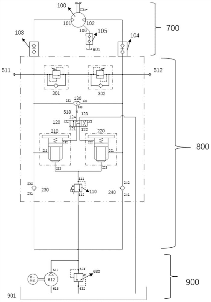
[0061] Such as figure 1 As shown, a hydraulic system for a loading test according to an embodiment of the present invention includes a loading input module 700, a hydraulic loading module 800, and a hydraulic auxiliary module 900. The hydraulic auxiliary module 900 includes a charge pump 612, an overflow valve 630 and Oil tank 901; the loading input module 700 includes a loading motor 100; the hydraulic loading module 800 includes an electric proportional overflow valve 110, an electromagnetic reversing valve 120, a shuttle valve 130, a first cartridge valve 210, a second cartridge valve Install valve 220, first one-way valve 230, second one-way valve 240 and controller 500;
[0062] The first valve port 211 and the second valve port 212 of the first cartridge valve 210 are respectively connected to the first o...
Embodiment 2
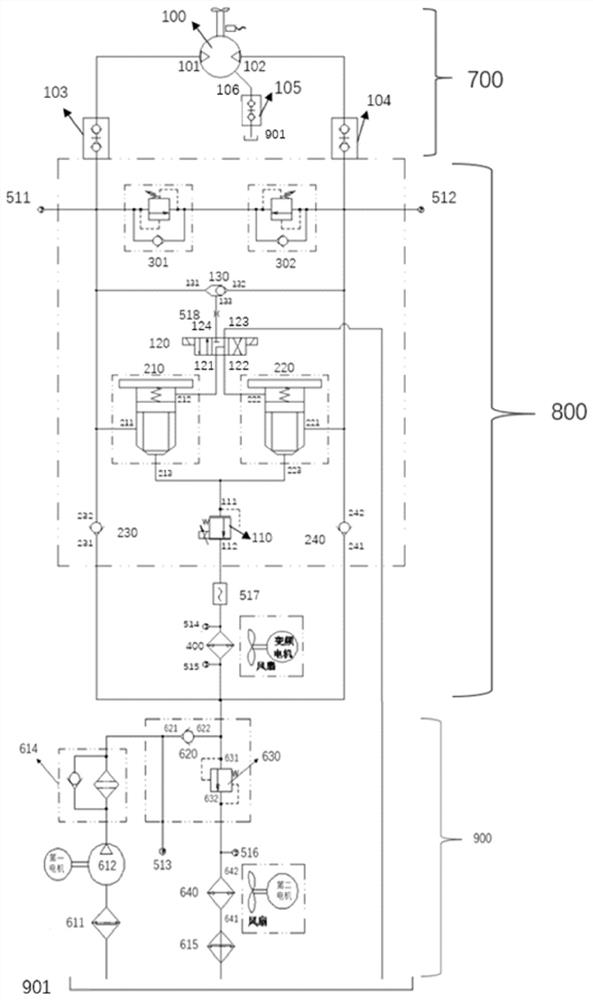
[0083] Such as figure 2 As shown, a hydraulic system for a loading test according to another embodiment of the present invention includes a loading input module 700 , a hydraulic loading module 800 , and a hydraulic auxiliary module 900 .
[0084] 1) The loading input module 700 includes a loading motor 100 .
[0085] 2) The hydraulic loading module 800 includes an electric proportional relief valve 110, an electromagnetic reversing valve 120, a shuttle valve 130, a first cartridge valve 210, a second cartridge valve 220, a first one-way valve 230, a second Check valve 240, first radiator 400 and controller 500;
[0086] The first valve port 211 and the second valve port 212 of the first cartridge valve 210 are respectively connected to the first oil port 101 of the loading motor and the first oil outlet 121 of the electromagnetic reversing valve 120;
[0087] The first valve port 221 and the second valve port 222 of the second cartridge valve are respectively connected to ...
PUM
Abstract
The invention relates to a hydraulic system and a control method for a loading test, comprising a loading motor, an electric proportional relief valve, an electromagnetic reversing valve, a shuttle valve, a first cartridge valve, a second cartridge valve, and a first one-way valve. valve, second check valve and controller; the three valve ports of the first cartridge valve are respectively connected to the first oil port of the loading motor, the first oil outlet of the electromagnetic reversing valve and the third port of the second cartridge valve valve port; the first valve port and the second valve port of the second cartridge valve are respectively connected to the second oil port of the loading motor and the second oil outlet of the electromagnetic reversing valve; the controller collects the feedback pressure value, according to the preset load , PID control algorithm, flow value and feedback pressure value to obtain control signals and then adjust the electric proportional relief valve, so that the difference between the feedback pressure value and the preset load is within the preset deviation threshold. Through the hydraulic system and the control method, the pressure in the hydraulic system can automatically follow the preset load to carry out the loading test, and the safety of the system is enhanced.
Description
technical field [0001] The invention relates to the technical field of hydraulic control, in particular to a hydraulic system and a control method for loading tests. Background technique [0002] In the process of product upgrading and new product development, corresponding test verification must be carried out, including performance tests and deeper durability reliability tests. These tests not only require empty state operation, but also require load tests that simulate different operating conditions. However, in the manufacturing industry, the load required for large-scale equipment loading is greater, and the complexity of the test is also higher, which involves the reciprocating motion and rotational motion of the actuator required for product verification. Higher requirements. [0003] Hydraulic loading is the most commonly used loading method in the existing rotating structure tests in the direction of studying the rotating motion and carrying out the loading test, w...
Claims
Application Information
Patent Timeline
Application Date:The date an application was filed.
Publication Date:The date a patent or application was officially published.
First Publication Date:The earliest publication date of a patent with the same application number.
Issue Date:Publication date of the patent grant document.
PCT Entry Date:The Entry date of PCT National Phase.
Estimated Expiry Date:The statutory expiry date of a patent right according to the Patent Law, and it is the longest term of protection that the patent right can achieve without the termination of the patent right due to other reasons(Term extension factor has been taken into account ).
Invalid Date:Actual expiry date is based on effective date or publication date of legal transaction data of invalid patent.